Clip advancer mechanism with alignment features

a technology of advancer mechanism and clip, which is applied in the field of surgical devices, can solve the problems of increasing the cost of clip appliers, inability to handle an overload applied to the jaws by the trigger, and overloading the jaws, and achieve the effect of limiting or preventing the vertical movement of the clip

Active Publication Date: 2013-09-03
CILAG GMBH INT
View PDF319 Cites 504 Cited by
  • Summary
  • Abstract
  • Description
  • Claims
  • Application Information

AI Technical Summary

Benefits of technology

[0008]The surgical clip applier can have a variety of configurations, and it can include a variety of features to facilitate advancement and formation of a surgical clip. In one embodiment, the surgical clip applier can include a feeder shoe that is slidably disposed within the elongate shaft and that is adapted to drive at least one surgical clip through the elongate shaft. In an exemplary embodiment, the feeder shoe can be adapted to move only in a distal direction, such that proximal movement of the feeder shoe is substantially prevented. The elongate shaft can also include a clip track disposed therein and adapted to seat at least one surgical clip. The feeder shoe can be slidably disposed within the clip track.
[0038]In other aspects, an improved endoscopic surgical clip applier is provided having jaws which close together to approximate tissues to be clipped and a clip advancing assembly adapted to sequentially advance a plurality of clips into the jaws. A ramped guide member is positioned just proximal to the opposed jaws and is adapted to align and guide a clip being advanced by the clip advancing assembly into the opposed jaws, and to limit or prevent vertical movement of the clip as the clip is being formed between the opposed jaws. In one embodiment, the ramped guide member can be formed on a tissue stop coupled to the opposed jaws, and the tissue stop can include a distal tip adapted to receive tissue therein to align the jaws with tissue to be clipped. In certain exemplary embodiments, the ramped guide member increases in height from a proximal end to a distal end thereof. The ramped guide member can be adapted to abut against an inferior surface of at least a portion of a clip being formed between the opposed jaws to limit or prevent vertical movement of the clip, i.e., pivoting of the apex and legs in a superior-inferior direction. In an exemplary embodiment, the ramped guide member has a maximum height of about 0.025″, and / or it is inclined at an angle in the range of about 5° to 45°.

Problems solved by technology

This need for precise timing and control has resulted in the need for complex mechanical designs, thereby increasing the cost of the clip appliers.
Other drawbacks of current clip appliers include the inability to handle an overload applied to the jaws by the trigger under a variety of conditions.
Many devices require full closure of the jaws, which can result in overload on the jaws when the vessel or duct positioned therebetween is too large to allow full closure, or when a foreign object is positioned between the jaws.

Method used


Image

  • Clip advancer mechanism with alignment features
  • Clip advancer mechanism with alignment features
  • Clip advancer mechanism with alignment features

Examples


Embodiment Construction

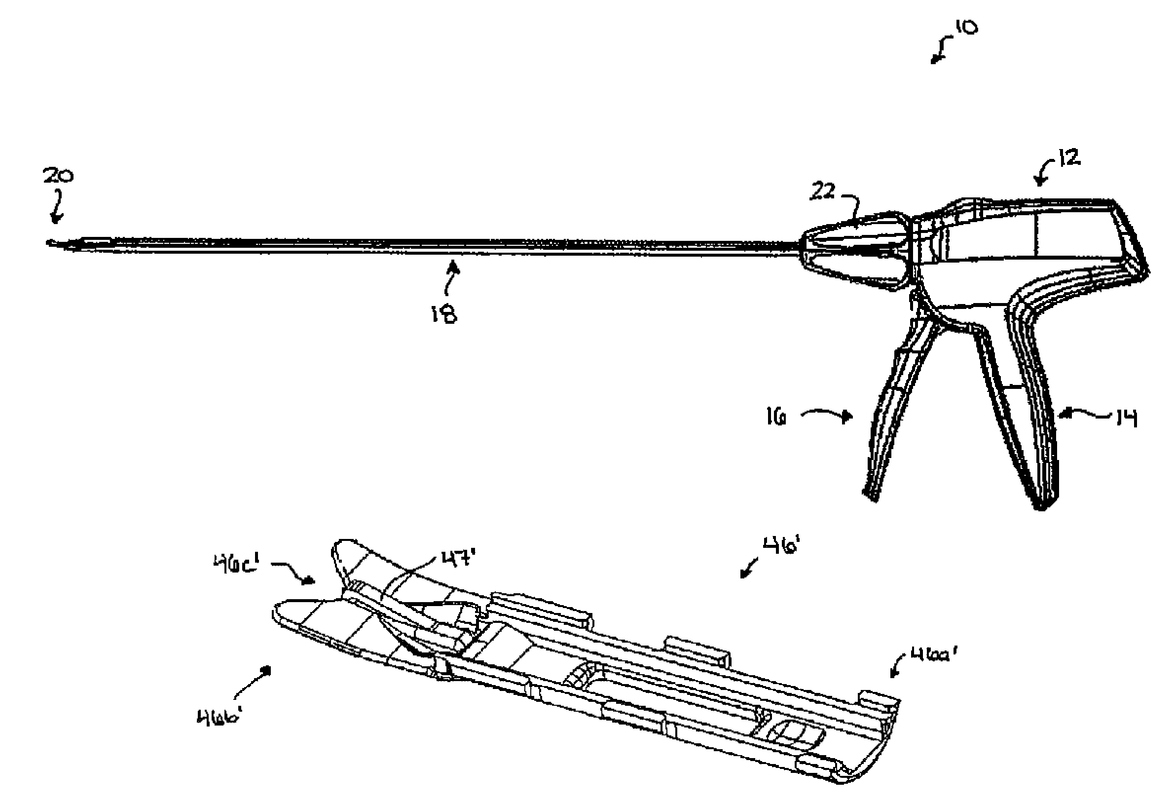
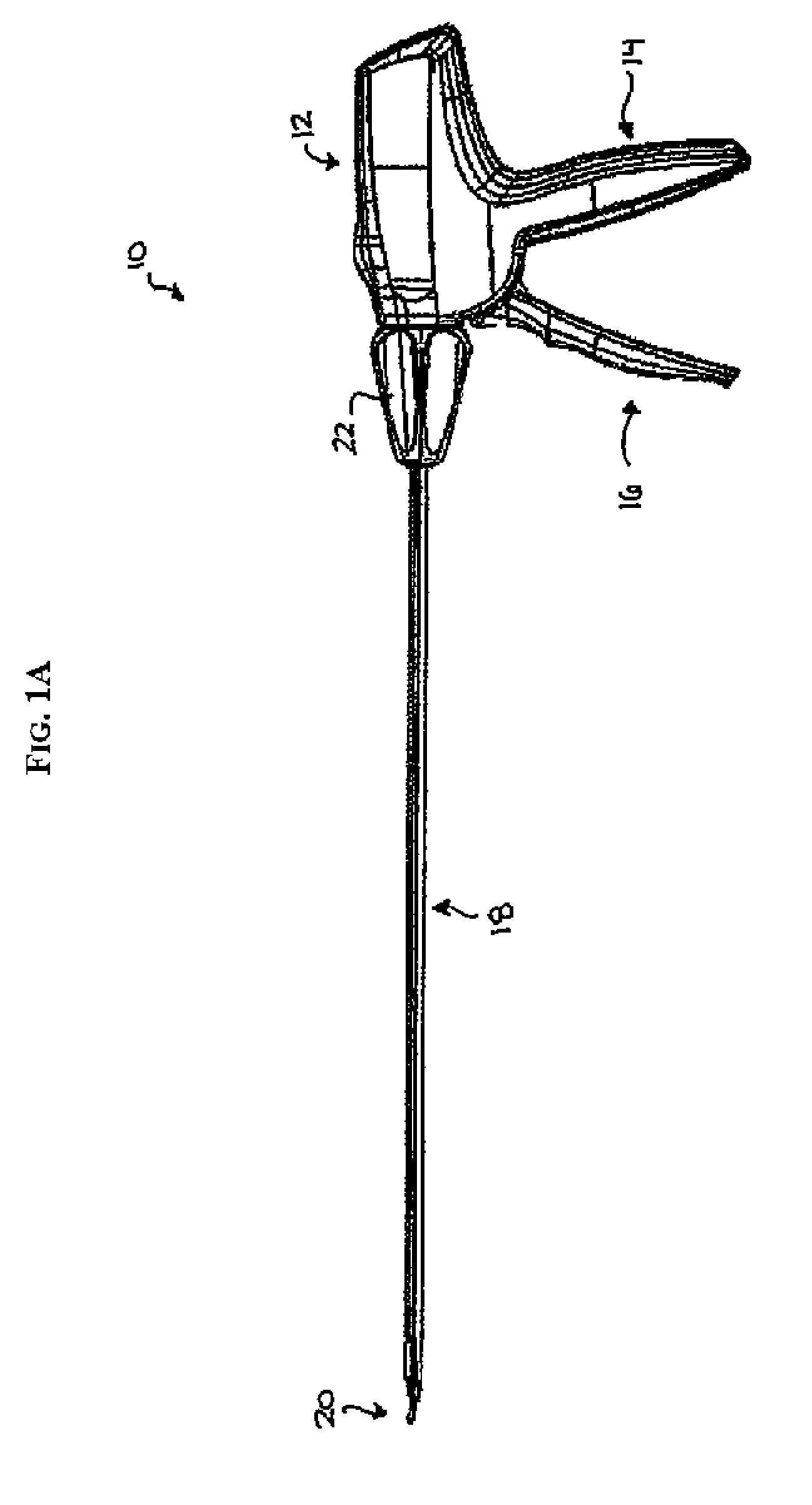
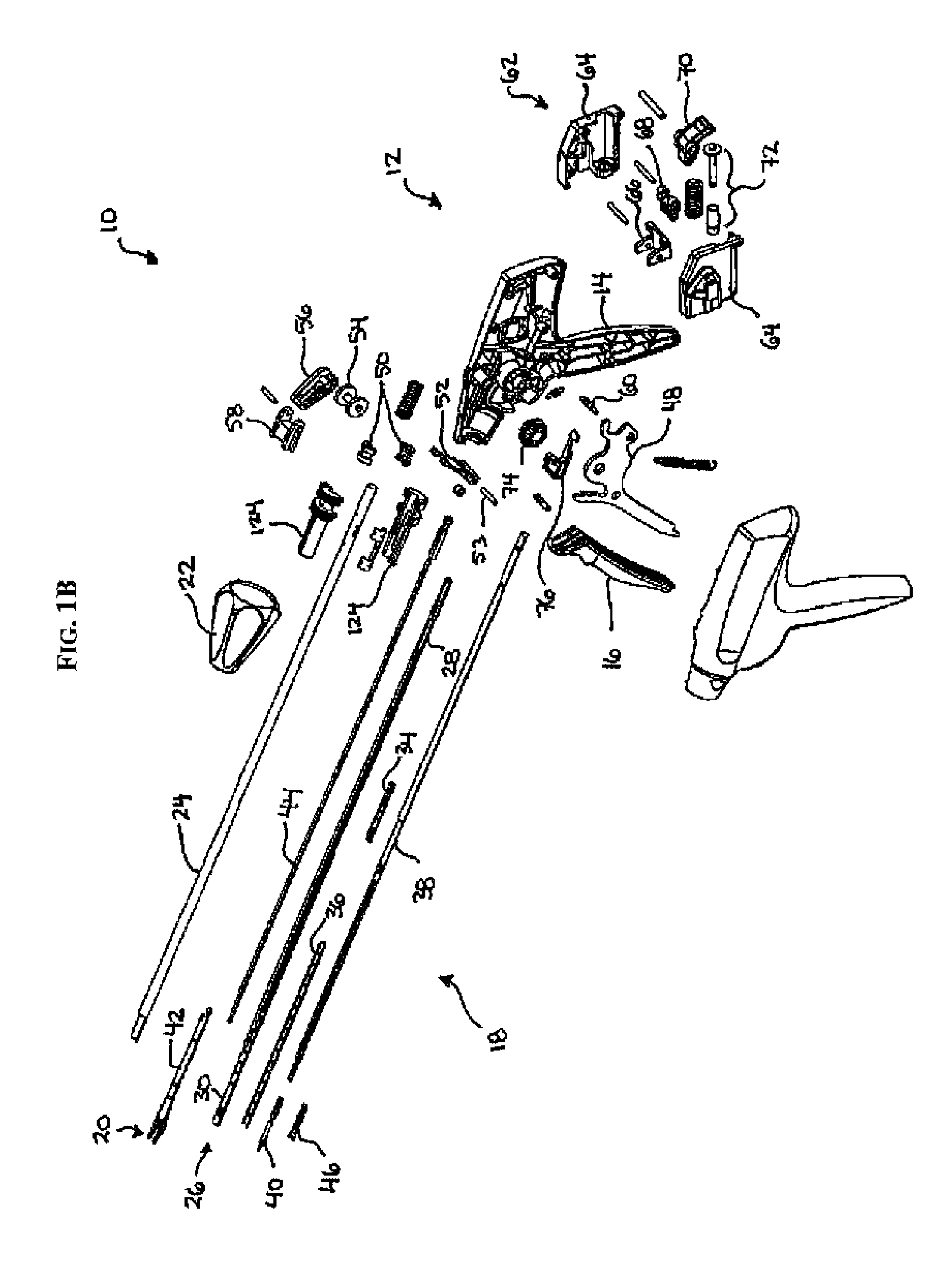
[0113]The present invention generally provides a surgical clip applier and methods for using a surgical clip applier to apply surgical clips to a vessel, duct, shunt, etc., during a surgical procedure. An exemplary surgical clip applier can include a variety of features to facilitate application of a surgical clip, as described herein and illustrated in the drawings. However, a person skilled in the art will appreciate that the surgical clip applier can include only some of these features and / or it can include a variety of other features known in the art. The surgical clip applier described herein is merely intended to represent certain exemplary embodiments.

[0114]FIG. 1A illustrates one exemplary surgical clip applier 10. As shown, the clip applier 10 generally includes a housing 12 having a stationary handle 14 and a movable handle or trigger 16 that is pivotally coupled to the housing 12. An elongate shaft 18 extends from the housing 12 and it includes a pair of opposed jaws 20 f...


PUM


Abstract

A surgical clip applier and methods for applying surgical clips to a vessel, duct, shunt, etc., during a surgical procedure are provided. In one exemplary embodiment, a surgical clip applier is provided having a housing with a trigger movably coupled thereto and a shaft extending therefrom with opposed jaws formed on a distal end thereof. The trigger is adapted to advance a clip to position the clip between the jaws, and to move the jaws from an open position to a closed position to crimp the clip positioned therebetween. The surgical clip applier can include a variety of features to facilitate use of the device, including features to align a clip with the jaws, features to prevent unintentional migration of a clip, and features to prevent clip fallout during formation.

Description

CROSS REFERENCE TO RELATED APPLICATIONS[0001]The present invention is a continuation-in-part of U.S. patent application Ser. No. 10 / 907,763 filed on Apr. 14, 2005, now U.S. Pat. No. 7,297,149 and entitled “Surgical Clip Applier Methods,” U.S. patent application Ser. No. 10 / 907,764 filed on Apr. 14, 2005, now U.S. Pat. No. 7,288,098 and entitled “Force Limiting Mechanism For Medical Instrument,” U.S. patent application Ser. No. 10 / 907,765 filed on Apr. 14, 2005, now U.S. Pat. No. 7,261,724 and entitled “Surgical Clip Advancement Mechanism,” U.S. patent application Ser. No. 10 / 907,766 filed on Apr. 14, 2005, now U.S. Pat. No. 7,686,820 and entitled “Surgical Clip Applier Ratchet Mechanism,” and U.S. patent application Ser. No. 10 / 907,768 filed on Apr. 14, 2005, now U.S. Pat. No. 7,731,724 and entitled “Surgical Clip Advancement And Alignment Mechanism.” These references are hereby incorporated by reference in their entirety.FIELD OF THE INVENTION[0002]The present invention relates bro...

Claims


Application Information

Patent Timeline
Patent Type & Authority Patents(United States)
IPC IPC(8): A61B17/068
CPCA61B17/10A61B17/1285A61B2019/302A61B2090/032A61B17/12A61B17/128
Inventor HUITEMA, THOMASKOCH, JR., ROBERTFUCHS, RICHARDMOLITOR, NICHOLAS
Owner CILAG GMBH INT
Why Eureka
Try Eureka