Heat exchanger housing and seals

a technology of heat exchanger and housing, applied in the field of heat exchangers, can solve the problems of reducing the compactness and cost-effectiveness of the heat exchanger, limiting the design thermal performance significantly, and using such configurations exacerbates the problem of flow bypassing in the tube and shell heat exchangers

Inactive Publication Date: 2005-10-25
LAIR LIQUIDE SA POUR LETUDE & LEXPLOITATION DES PROCEDES GEORGES CLAUDE
View PDF18 Cites 25 Cited by
  • Summary
  • Abstract
  • Description
  • Claims
  • Application Information

AI Technical Summary

Benefits of technology

[0013]The present invention also advantageously provides a heat exchange apparatus including a housing, a first fluid passageway provided within the housing, a second fluid passageway provided within the housing, and a baffle plate substantially separating the first fluid passageway from the second fluid passageway. The apparatus also includes an array of fluid conduits provided within the housing, where the array of fluid conduits extends through the first fluid passageway, the baffle plate, and the second passageway. A plate member is provided within the first fluid passageway. The array of fluid conduits extends through the plate member, and the plate member is mounted to outer surfaces of the array of fluid conduits at a predetermined distance from the baffle plate. At least one layer of intumescent material is provided between the baffle plate and the plate member, and the array of fluid conduits extends through the at least one layer of intumescent material. The at least one layer of intumescent material substantially entirely fills a gap between the baffle plate and the plate member.

Problems solved by technology

It is known that flow leakage bypassing the flow passages outside the surfaces of the tubes, commonly referred to as the “shell side” of the “tube and shell” exchanger, limits design thermal performance significantly.
However, the use of such configurations exacerbates the problem of flow bypassing in tube and shell heat exchangers.
Therefore, the heat exchanger industry has attempted to limit the effects of flow bypassing by decreasing pressure drop through the flow passages by spacing the tubes far apart and by providing little or no extended heat transfer surfaces (often referred to as fins), which decrease the compactness and cost-effectiveness of the heat exchanger.
However, these methods of limiting flow bypassing have several severe limitations.
Such elements are limited to tubular heat exchange arrays having a rounded plan form, such as those referred to as tube and shell exchangers.
Further, these elements are limited in their ability to seal against surfaces of high roughness or local surface imperfection.
The '822 patent describes a method that is relatively impractical, since many tube and shell exchangers have a rounded shell manufactured by welding rolled plates, and thus local irregularities can only be removed by difficult and / or costly machining or grinding.
In many cases, due to the physical size or material of construction, it would be completely impractical to improve the surface finish enough to utilize the method described in the '822 patent.
Finally, the metal elements of the invention in the '822 patent are limited to applications below the temperature where creep deformation begins.
In fact, even utilizing the metal elements at operation temperatures that are high enough to stress-relieve the metal elements will render them substantially less effective in providing sealing.
Thus, temperatures above 400° C. are completely out of the question, and temperatures above 200° C. may cause partial loss of function over long exposures.
However, the elastic elements described in the '722 patent have even more severe temperature limits than the elastic elements described in the '822 patent.
The problems of limiting bypass flow using seals are made worse in heat exchangers with exceptionally high local pressure gradients in the flow passages outside the tubes.
This indicates the inability of prior art methods to prevent deleterious leakage in such designs.
The burner required in the apparatus described in the '856 patent can create a significant pressure drop across the partition between the flow channels.
This pressure drop significantly increases deleterious flow bypassing using conventional construction techniques.

Method used


Image

  • Heat exchanger housing and seals
  • Heat exchanger housing and seals
  • Heat exchanger housing and seals

Examples


Embodiment Construction

[0022]Embodiments of the present invention will be described hereinafter with reference to the accompanying drawings. In the following description, the constituent elements having substantially the same function and arrangement are denoted by the same reference numerals, and repetitive descriptions will be made only when necessary.

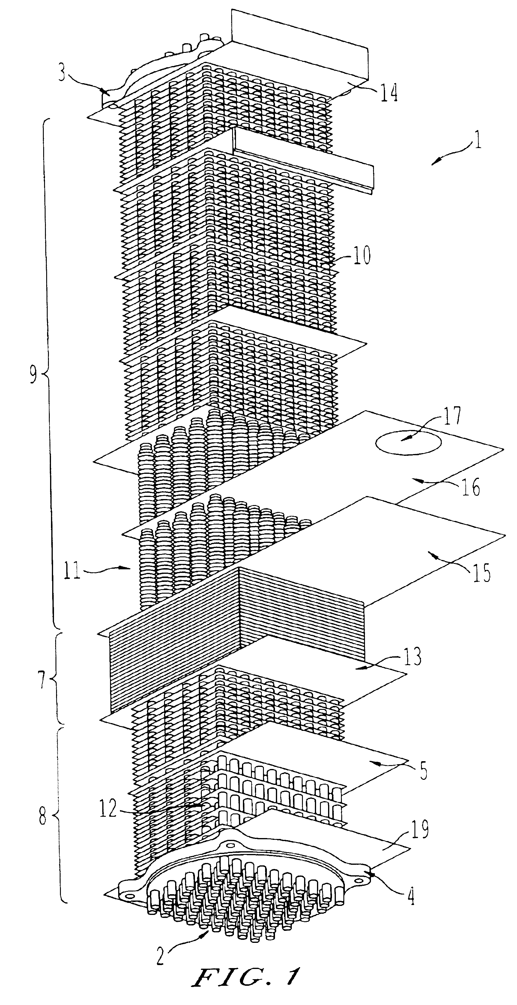
[0023]FIG. 1 shows a tubular heat exchanger core including an array of substantially-parallel conduits or tubes 2, which are sealingly connected between a first tubesheet 3 and a second tubesheet 4. A first fluid flows from an inlet manifold sealingly attached to the first tubesheet 3, through tubes of the array of tubes 2, and out a second manifold attached to the second tubesheet 4. The manifolds are not shown here for the sake of clarity. The array of tubes 2 is provided on outer surfaces of the tubes with flow directing baffles or plates 5, which are used to cause a second fluid to flow substantially normal to the axis of the array of tubes 2. One or m...


PUM


Abstract

A housing for a heat exchange apparatus including a fluid passageway partially defined by a baffle plate having an extended portion. The heat exchange apparatus further includes an array of fluid conduits extending through the fluid passageway. The housing includes a plurality of housing members each having a wall and at least one flange extending from the wall. The flanges of adjacent housing members are joined at a flange joint, and the flange joint is configured to fixedly receive the extended portion of the baffle plate. The apparatus also includes a plate member is provided within the fluid passageway and intumescent material fills a gap between the baffle plate and the plate member. Additionally, a second baffle plate is provided that defines a portion of a second fluid passageway, where a refractory gasket and a layer of intumescent material are provided between the first and second baffle plates.

Description

BACKGROUND OF THE INVENTION[0001]1. Field of the Invention[0002]The present invention relates generally to heat exchangers and methods of constructing heat exchangers.[0003]2. Discussion of the Background[0004]Heat exchangers and heat exchange chemical reactors having large arrays of parallel tubes are known in the art. Traditional design practices for such articles are codified in design standards. It is known that flow leakage bypassing the flow passages outside the surfaces of the tubes, commonly referred to as the “shell side” of the “tube and shell” exchanger, limits design thermal performance significantly.[0005]Various techniques are used to advantageously increase heat transfer area per unit volume in heat exchangers, such as the use of tubes with extended heat transfer surfaces and the use of an especially-closely packed array of tubes. Such configurations are of important in the construction of compact, cost-effective heat exchange structures. However, the use of such conf...

Claims


Application Information

Patent Timeline
Patent Type & Authority Patents(United States)
IPC IPC(8): F28F9/22F28D7/16F28D7/00F28F9/00
CPCF28D7/1653F28F9/001F28F9/22F28F2230/00F28D1/00F28D5/00F28D7/00F28D9/00
Inventor LOMAX, JR., FRANKLIN D.LIM, KIM HONGWAIDE, STEPHEN
Owner LAIR LIQUIDE SA POUR LETUDE & LEXPLOITATION DES PROCEDES GEORGES CLAUDE
Why Eureka
Try Eureka