
Fuse structure

a fuse and structure technology, applied in the field of fuse, can solve the problems of fuses blowing, blown fuse, and difficulty in reliably blowing fuses on a consistent basis

Inactive Publication Date: 2005-11-01
HEWLETT PACKARD DEV CO LP
View PDF26 Cites 23 Cited by
  • Summary
  • Abstract
  • Description
  • Claims
  • Application Information

AI Technical Summary

Benefits of technology

The solution enables consistent and reliable blowing of fuses using lower voltages, minimizing damage to surrounding layers and predicting the required voltage, thereby improving the reliability of the fuse-blowing process and reducing variability.

Problems solved by technology

The fuses may be blown during the manufacturing process or afterwards.
Oftentimes there is difficulty in reliably blowing the fuses on a consistent basis.
Variability in manufacture can result in some fuses blowing at a given voltage while others will not.
This can result in some fuses that are intended to exhibit a substantially open-circuit resistance exhibiting a substantially closed-circuit resistance instead.
Fuses can also “under blow,” meaning that they are partially but not completely blown.
However, too much voltage can cause fuses to “over blow,” meaning that they blow too vigorously, perhaps causing damage to other layers of the fuse structure.
Variability in temperature from one fuse to another is another factor that contributes to the difficulty in blowing fuses reliably and consistently.
Not only do the factors described above combine to increase the uncertainty that a fuse can be blown, but they also introduce uncertainty into the fuse-blowing process.
For example, it can be more difficult to identify beforehand what voltage should be used to blow the appropriate fuses.

Method used


Image

  • Fuse structure
  • Fuse structure
  • Fuse structure

Examples


Embodiment Construction

[0019]Reference will now be made in detail to various embodiments of the invention, examples of which are illustrated in the accompanying drawings. While the invention will be described in conjunction with these embodiments, it will be understood that they are not intended to limit the invention to these embodiments. On the contrary, the invention is intended to cover alternatives, modifications and equivalents, which may be included within the spirit and scope of the invention as defined by the appended claims. Furthermore, in the following description of the present invention, numerous specific details are set forth in order to provide a thorough understanding of the present invention. In other instances, well-known methods, procedures, components, and circuits have not been described in detail as not to unnecessarily obscure aspects of the present invention.

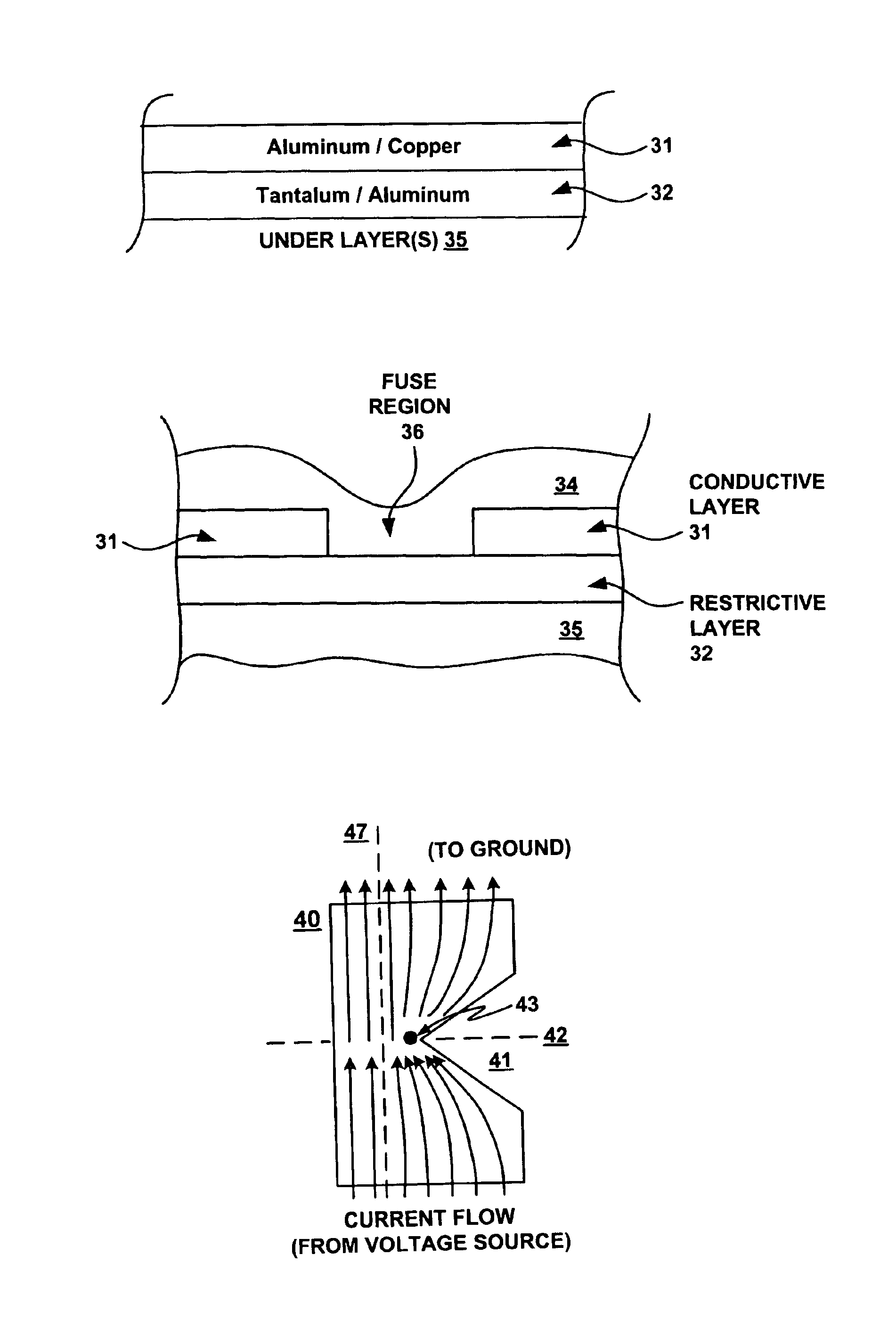
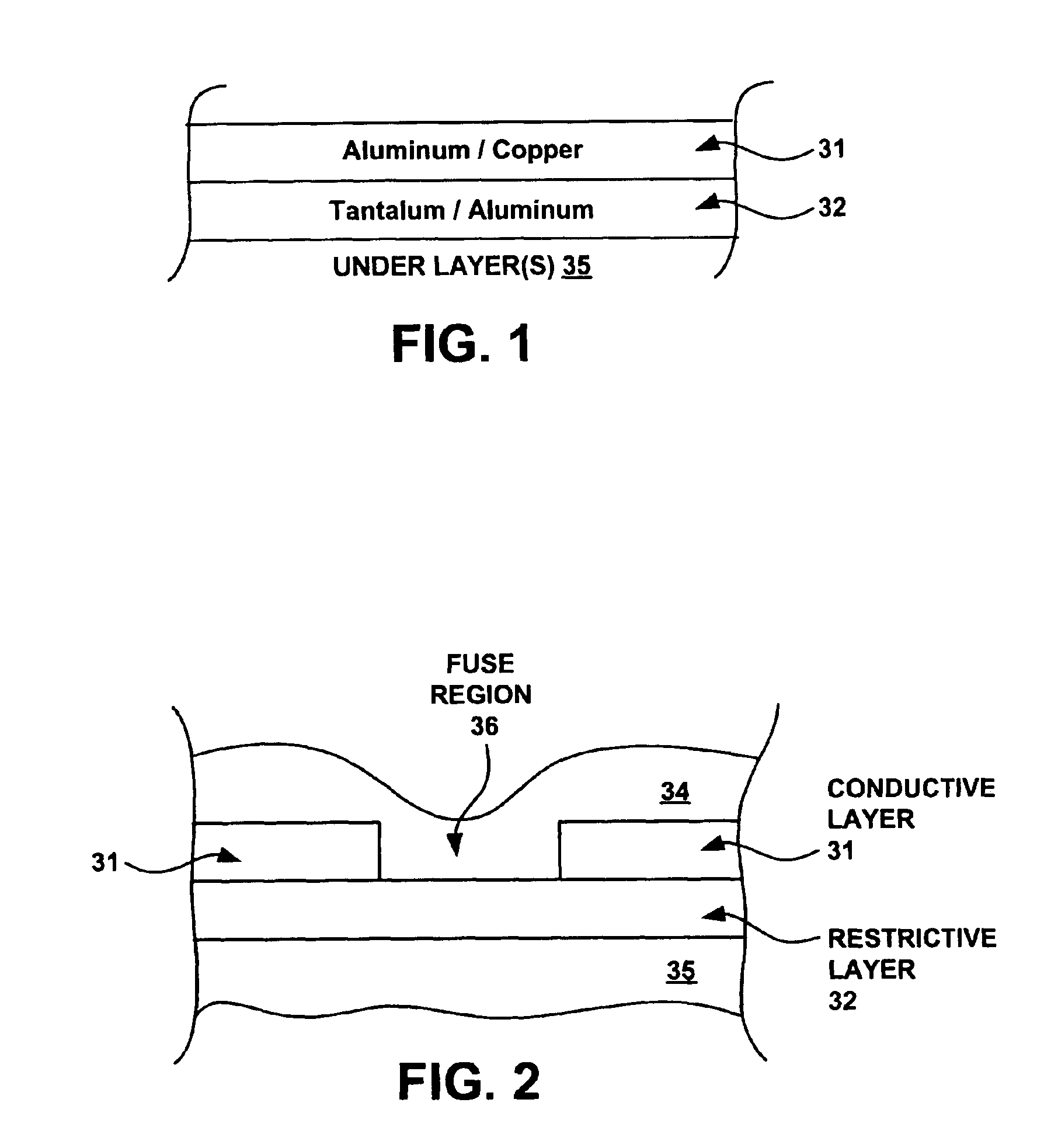
[0020]FIG. 1 is a cross-sectional view showing certain layers in a stack 30 used in forming a fuse structure according to on...


PUM


Abstract

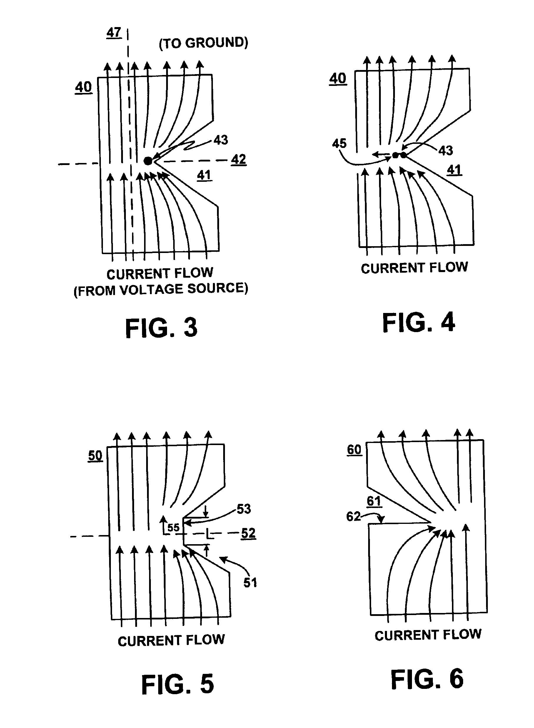
A fuse structure is described. The fuse structure includes a first region adapted to be coupled to a voltage source, a second region adapted to be coupled to a ground, and a current flow region disposed between the first and second regions. The current flow region has a configuration that causes a void to be opened at a point of localized heating due to current crowding within the current flow region and that causes the void to propagate across the current flow region.

Description

BACKGROUND[0001]Fuses, or more specifically micro fuses, can be used to encode (store) information in devices such as removable printer components (e.g., ink cartridges) used in printer systems. For example, a device can include a number of fuses. A blown fuse has a higher, or substantially open-circuit, resistance, while a non-blown fuse has a lower, or substantially closed-circuit, resistance. Information can be encoded depending on which fuses are blown or the particular combination of blown fuses. In a printer system, the type of information encoded may include, for example, identification of the type of product, the amount of ink provided by an ink cartridge, and the value of a thermal sense resistor associated with the ink cartridge.[0002]The fuses may be blown during the manufacturing process or afterwards. Oftentimes there is difficulty in reliably blowing the fuses on a consistent basis. Variability in manufacture can result in some fuses blowing at a given voltage while ot...

Claims


Application Information

Patent Timeline
Patent Type & Authority Patents(United States)
IPC IPC(8): H01L23/525G11C17/14H01L23/52G11C17/16
CPCG11C17/16H01L23/5256H01L2924/0002H01L2924/00
Inventor LEIGH, STAN E.ABADILLA, TOM P.SCHULTE, DONALD W.MCMAHON, TERRY
Owner HEWLETT PACKARD DEV CO LP
Learn More