Mobile speedometer system and associated methods

Inactive Publication Date: 2005-11-08
NIKE INC
View PDF46 Cites 117 Cited by
  • Summary
  • Abstract
  • Description
  • Claims
  • Application Information

AI Technical Summary

Benefits of technology

[0009]It is yet another object of the invention to provide improvements to sporting devices which are ri

Problems solved by technology

However, athletes in such sporting activities typically onl

Method used


Image

  • Mobile speedometer system and associated methods
  • Mobile speedometer system and associated methods
  • Mobile speedometer system and associated methods

Examples


Embodiment Construction

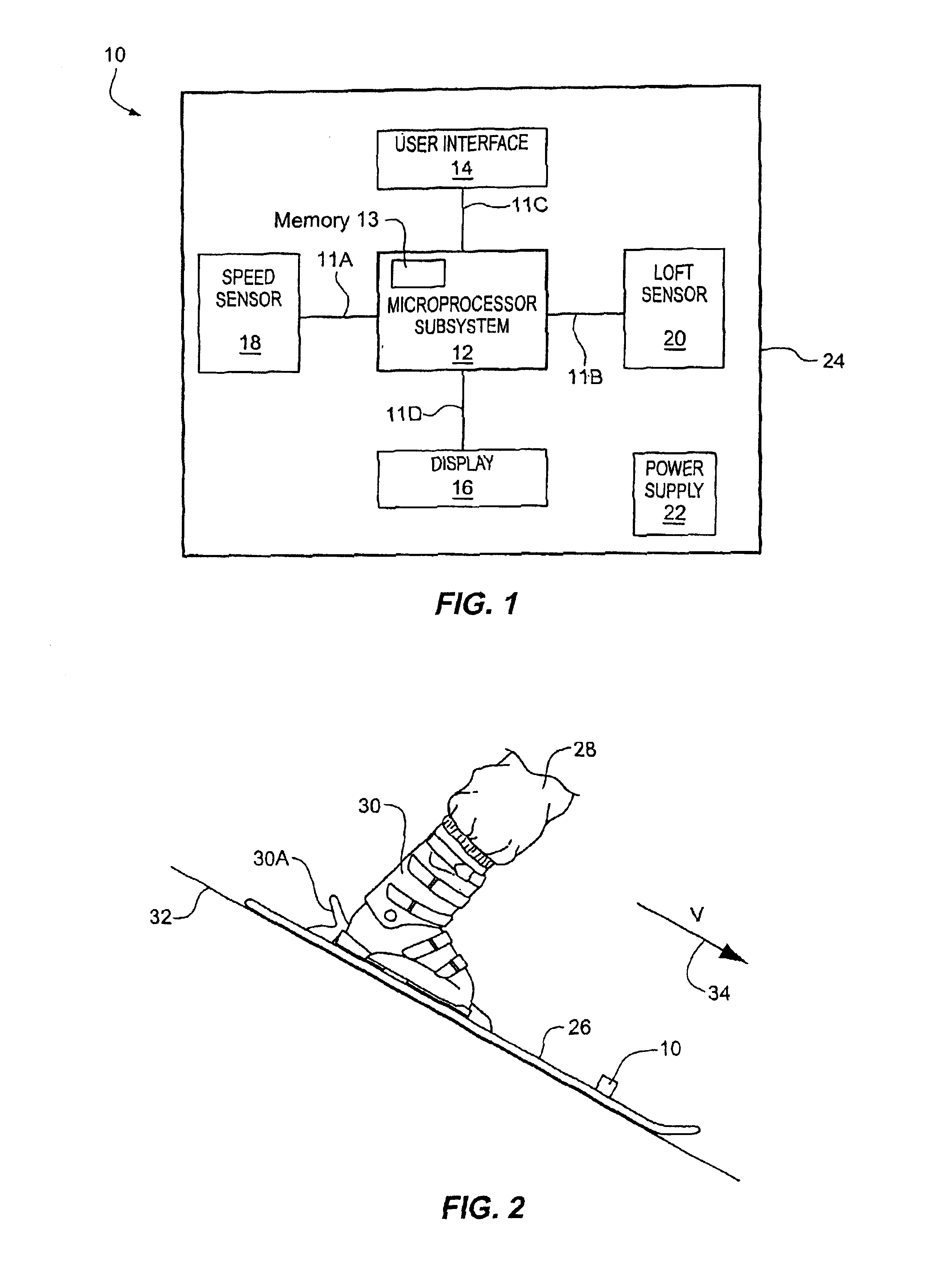
[0051]FIG. 1 illustrates a system 10 constructed according to the invention. A microprocessor subsystem 12 controls the system 10 and connects to a user interface 14, a display 16, speed sensor 18 and loft sensor 20. A power supply 22, e.g., a battery, provides power to the system 10 and connects to the components 12,14,16,18 and 20 via appropriate electrical interconnections (not shown). The microprocessor subsystem 12 includes memory 13 for storing data acquired by the system 10.

[0052]The system 10 is incorporated into a relatively small housing, shown by the outline 24. The housing 24 is preferably arranged to protect the components 12,14,16,18 and 20 from the elements of nature—such as rain, snow, sand and dust, each of which is expected during the ordinary course of usage on a ski slope and / or mountain bike trail. In addition, the housing 24 is attachable to a sporting vehicle, such as a ski or mountain bike, by means such as a glue or a mechanical mount, e.g., screws. Alternat...


PUM


Abstract

The invention detects loft time and/or speed of a vehicle and/or person during activities of moving and jumping. A loft sensor detects leaving the ground and returning to the ground. A microprocessor subsystem converts the sensed information to determine a loft time. A display shows the recorded loft time to a user of the system. A speed sensor can detect speed for selective display to the user, and height may also be determined during airtime.

Description

RELATED APPLICATION[0001]This application is a continuation of U.S. application Ser. No. 09 / 784,783 filed Feb. 15, 2001, now U.S. Pat. No. 6,516,284, which is a continuation of U.S. Ser. No. 09 / 353,530, filed Jul. 14, 1999, now U.S. Pat. No. 6,496,787, which is a continuation of U.S. Ser. No. 08 / 764,758 (now U.S. Pat. No. 5,960,380), filed Dec. 12, 1996, which is a continuation of U.S. Ser. No. 08 / 344,485 (now U.S. Pat. No. 5,636,146), filed Nov. 21, 1994, each of which are incorporated herein by reference.FIELD OF THE INVENTION[0002]The invention relates generally to the measurement of the loft time and speed of a person or vehicle relative to ground.BACKGROUND OF THE INVENTION[0003]It is well known that many skiers enjoy high speeds and jumping motions while traveling down the slope. High speeds refer to the greater and greater velocities which skiers attempt in navigating the slope successfully (and sometimes unsuccessfully). The jumping motions, on the other hand, include moveme...

Claims


Application Information

Patent Timeline
IPC IPC(8): G01P3/42G01P3/50G04F8/00G04F8/08A63B71/06G01S11/00G01S15/60G01S15/00G01S11/14A63B69/18
CPCA61B5/11G01P3/50G04F8/08A61B2562/0219A63B71/0605A63B2069/185G01S11/14G01S15/60A61B5/6895A61B5/6807
Inventor FLENTOV, PETERDARCY, DENNIS M.VOCK, CURTIS A.
Owner NIKE INC
Why Eureka
Try Eureka