Product management display system

a product management and display system technology, applied in the direction of racks, show hangers, cabinets, etc., can solve the problems of incorrect installation of parts, waste of time, etc., and achieve the effect of smooth pushing and less binding

Inactive Publication Date: 2005-11-15
RTC IND
View PDF74 Cites 227 Cited by
  • Summary
  • Abstract
  • Description
  • Claims
  • Application Information

AI Technical Summary

Benefits of technology

[0010]In accordance with an illustrative embodiment of the invention, a T assembly and / or a full track may be coupled to a front rail via a complimentary tongue and groove arrangement. Any of the components having a divider panel, such as a T assembly, an end finisher, and a full-width track, may also contain any of various engagement mechanisms for non-slidably engaging with a front rail's corresponding engagement mechanism. For instance, teeth on a base may engage corresponding teeth on the front rail. Teeth of this type advantageously allow a T assembly, full-width track, and / or end finishers with corresponding teeth to be located at positions virtually continuously along the front rail and may prevent the components from being moved unintentionally from their intended positions during normal shopping activity and shelf re-stocking.
[0012]In accordance with an illustrative embodiment of the invention, a pusher track may include a depression, which may be used while re-stocking merchandise to hold a pusher near the back of a frill-width track or T assembly. To use the depression to hold a pusher at the back of the track, a person may move the pusher back to the depression and may tilt the top of the pusher toward the front of the track. Merchandise may be re-stocked without having to manually hold the pusher out of the way. To remove the pusher from the depression, the pusher may be pushed toward the back of the track, the pusher will then return to an upright position and move along the track in its usual way.

Problems solved by technology

This presents store personnel with potentially confusing choices, which may lead to frustration, wasted time, and incorrectly installed parts.

Method used


Image

  • Product management display system
  • Product management display system
  • Product management display system

Examples


Embodiment Construction

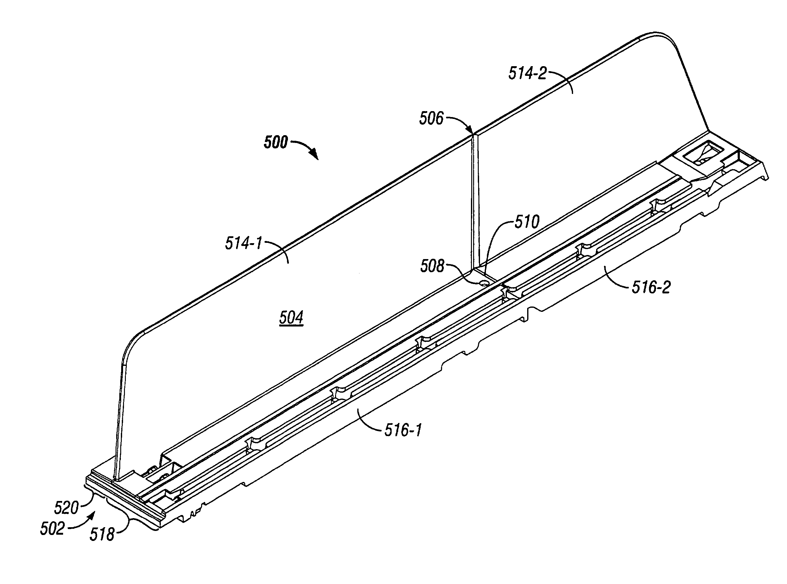
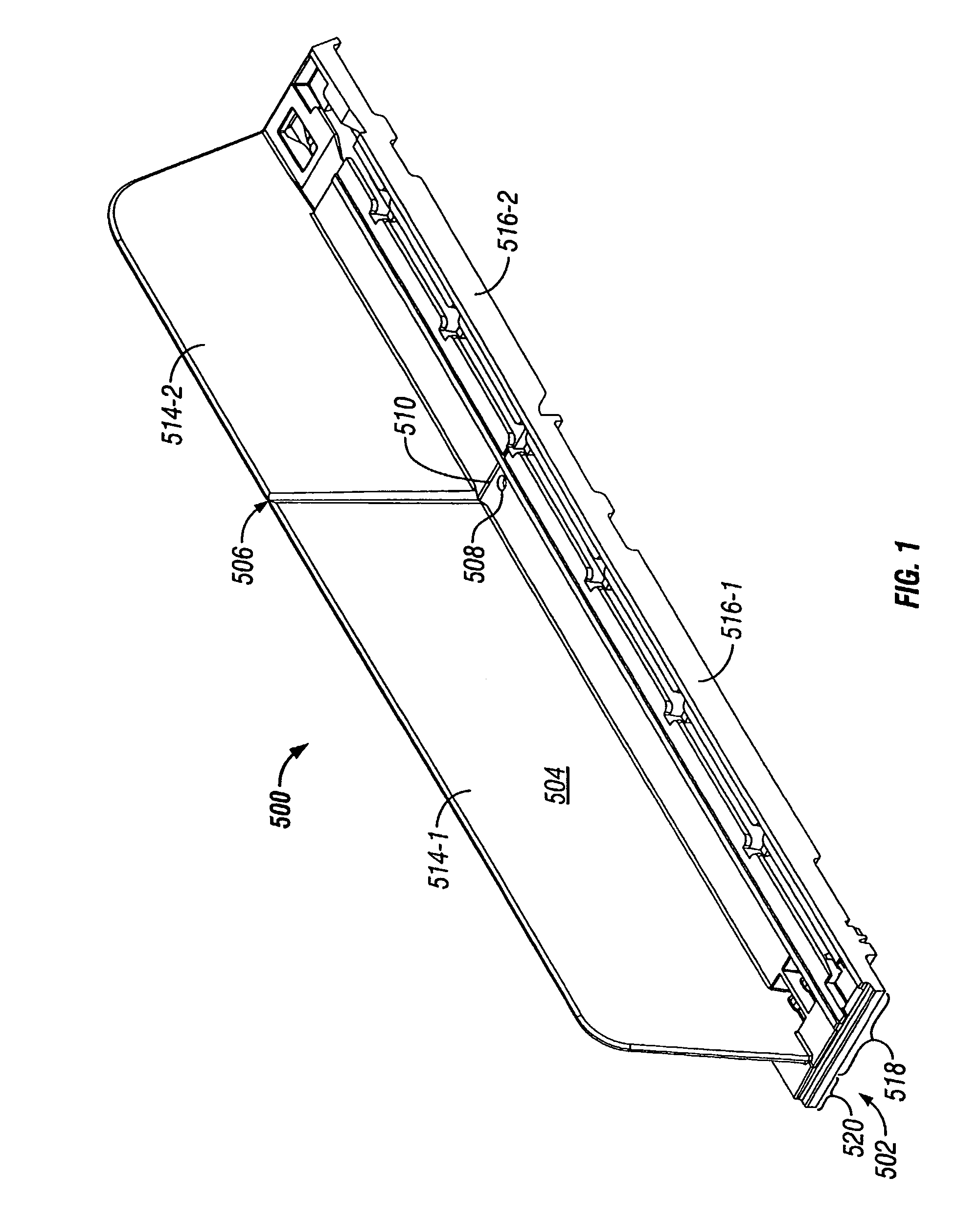
[0027]FIG. 1 depicts an integrated “T” assembly 500 in accordance with an illustrative embodiment of the invention. The “T” refers to the appearance of the T assembly 500 as viewed in the direction of arrow 502 in FIG. 5. T assembly 500 would actually look like an upside-down (and off-center) T, but for the sake of brevity, it is referred to simply as a T assembly. The T assembly may also be referred to as a base-and-divider assembly. The T assembly essentially combines into a single assembly, a first track, a divider, and a second track. In accordance with an illustrative embodiment of the invention, the divider portion 504, the first portion 518 of the base, and the second portion of the base 520 may be manufactured as a single integrated component.

[0028]In accordance with an illustrative embodiment of the invention shown in FIG. 1, a divider 504 may divide the base of the T assembly 500 into a first portion 518 and a second portion 520. The first portion 518 of the base may be re...


PUM


Abstract

An integrated “T” assembly (500) combines into a single integrated assembly, a track portion along both sides of a divider (504). The T assembly may have a wide-base portion (518), which may include a spring-urged-pusher track, on one side of the divider and a narrow-base portion (520) on the opposite side of the divider. An offset pusher (700) may have an upper portion that is offset, via an angled offset portion, from a lower portion of the pusher. Additional supporting bases, any of which may include spring-urged-pusher tracks and / or a spring-urged pusher, may be used under a wide product. Left and right side finisher (600) components may be paired with T assemblies near the sides of a merchandise-display shelf. The T assembly, base, and / or end finishers may be coupled to a front rail via a complimentary tongue and groove arrangement and / or a non-slidable engagement, such as mating teeth.

Description

CROSS REFERENCE TO RELATED APPLICATIONS[0001]This application claims priority to provisional U.S. Application Ser. No. 60 / 291,732, filed May 17, 2001, entitled Product Management Display System.FIELD OF THE INVENTION[0002]The invention relates to a system for displaying, pushing, and dividing merchandise on merchandise-display shelves.BACKGROUND OF THE INVENTION[0003]It is desirable to have merchandise on a shelf situated toward the front of the shelf so that the merchandise is visible and accessible to shoppers. Thus, as merchandise is removed from a shelf, it may be advantageous to push the remaining merchandise toward the front of the shelf. It may also be desirable to include dividing panels, also referred to as dividers, to separate merchandise into rows on a display shelf.[0004]Commonly assigned U.S. Pat. No. 6,041,720 (“the '720 patent”) discloses a product management display system that may be used for dividing and pushing displayed merchandise.[0005]DE 299-02,688 U1 disclos...

Claims


Application Information

Patent Timeline
Patent Type & Authority Patents(United States)
IPC IPC(8): A47F1/12A47F1/00A47B57/00A47B65/00A47F5/00H04M3/42
CPCA47F1/126A47F5/005A47F1/04
Inventor HARDY, STEPHEN N.
Owner RTC IND
Why Eureka
Try Eureka