
Two directional crossing gate arm protection assembly

a protection assembly and gate arm technology, applied in the direction of traffic gates, ways, transportation and packaging, etc., can solve the problems of gate arms being damaged by passing vehicles, gate arms can be broken, pedestrians and vehicular traffic can be exposed to improperly guarded train crossings, and the gate arm can suffer damage from passing vehicles,

Inactive Publication Date: 2005-11-22
WESTERN CULLEN HAYES
View PDF11 Cites 19 Cited by
  • Summary
  • Abstract
  • Description
  • Claims
  • Application Information

AI Technical Summary

Problems solved by technology

When lowered to their horizontal position, gate arms can suffer damage from passing vehicles, wind pressure and vandalism.
Damage frequently results in broken gate arms that sever at their point of attachment to a crossing gate assembly.
Such damage risks exposing pedestrians and vehicular traffic to improperly guarded train crossings.
However, Barvinek suffers from numerous problems.
Relying on cam blocks and ball bearings, Barvinek is expensive to manufacture, monitor and maintain.
Moreover, Barvinek cannot return a displaced gate arm to a position parallel with the groove of the camblock if the gate mechanism rises while the gate is displaced.
Finally, Barvinek provides no control over the rate of gate arm return and cannot prevent gate arm over travel into the flow of traffic.
However, Tamenne also suffers from numerous problems.
Tamenne's hydraulic piston system, like Barvinek's camblock and ball bearing system, is expensive to manufacture, monitor and maintain.
Further, Tamenne's weight channel counterbalance places an imbalanced strain on the gate arm pivot assembly, risking damage to the gate arm mechanism.
Like Bamivek, Tamenne is incapable of returning a displaced gate arm back to its normal position if the gate mechanism rises while the gate is displaced.
The Pease I assembly is limited, however, to a single direction of rotation.

Method used


Image

  • Two directional crossing gate arm protection assembly
  • Two directional crossing gate arm protection assembly
  • Two directional crossing gate arm protection assembly

Examples


Embodiment Construction

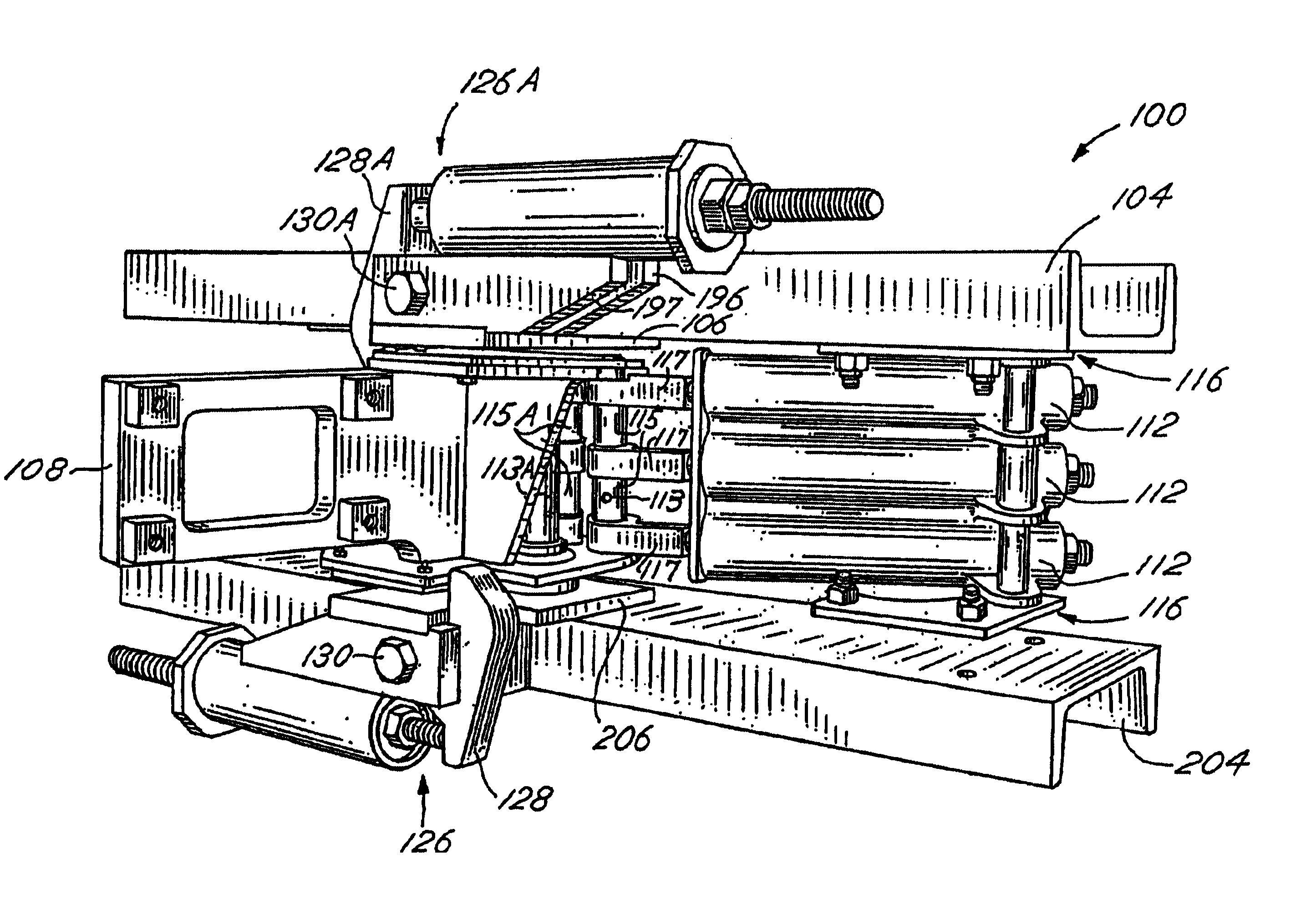
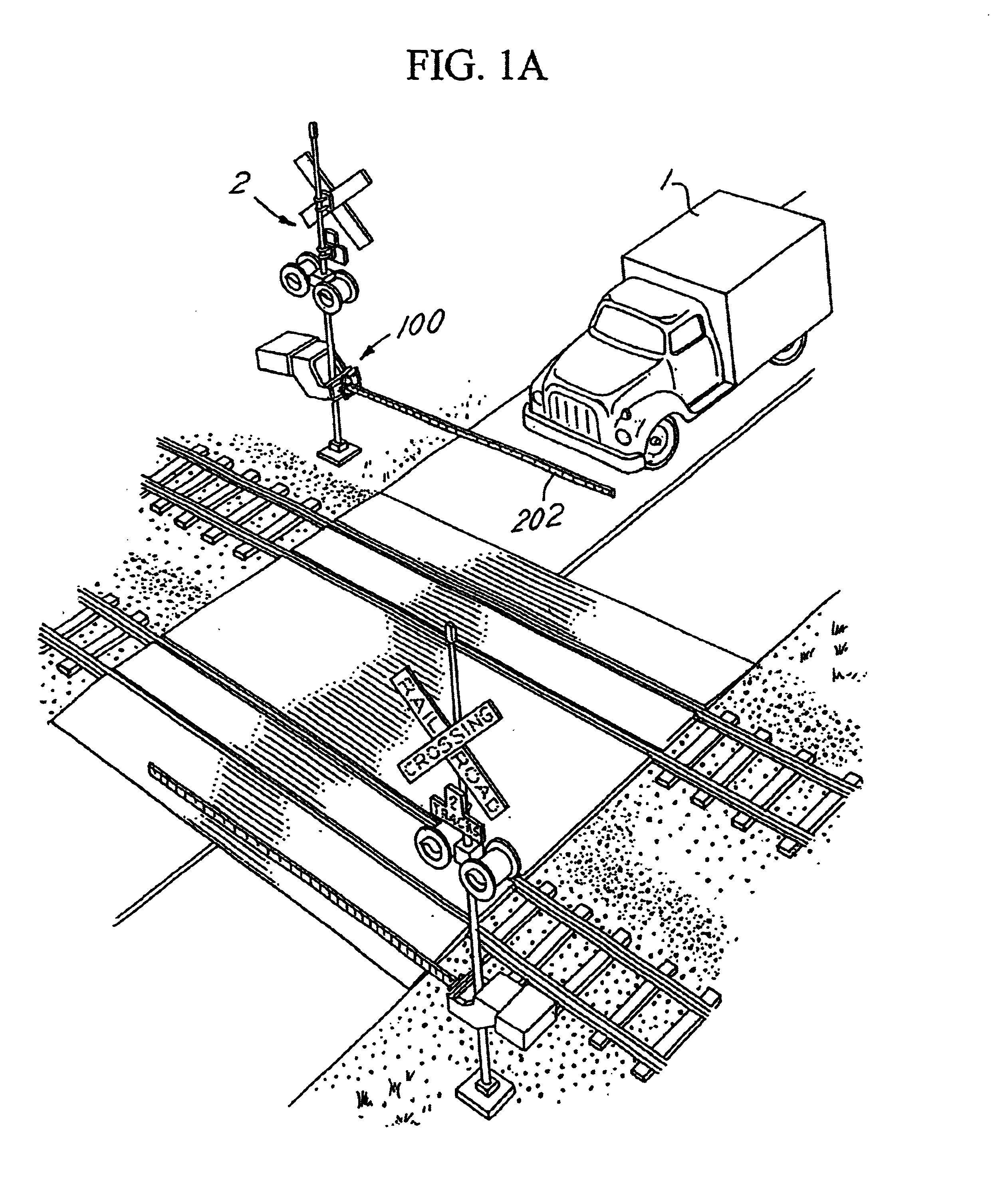
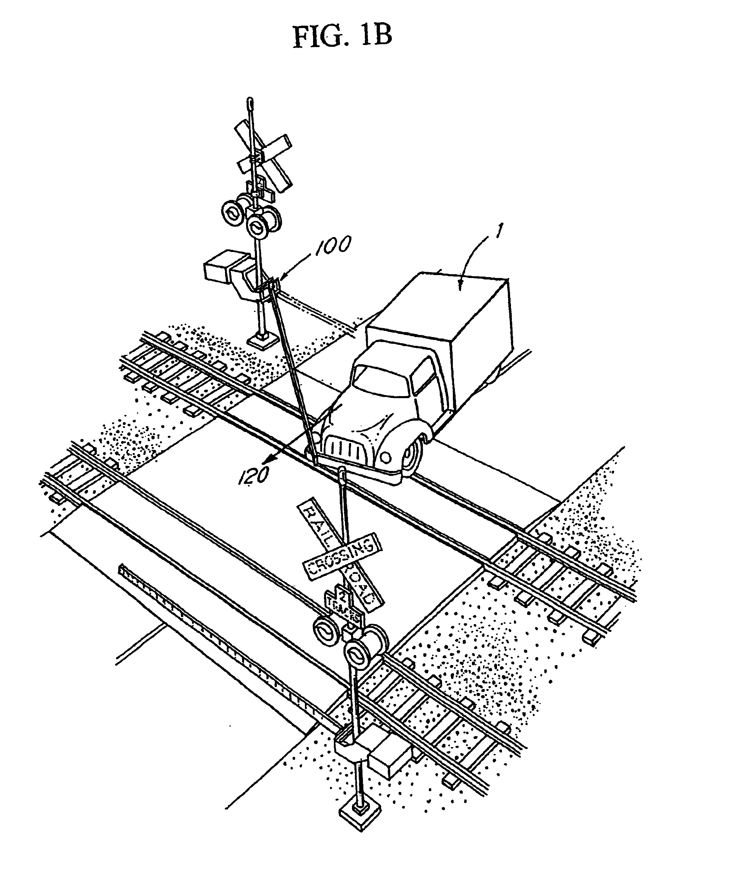
[0018]The present invention can be more fully understood with reference to FIGS. 1-7A. FIGS. 1A, 1B, and 1C are perspective views of a crossing gate assembly, generally, 100 in operation. Normally, the crossing gate assembly 100 is in a substantially upright position (not shown), holding a crossing gate arm 202 in a generally vertical orientation allowing vehicles 1 to proceed through a railroad crossing in the absence of train traffic. When actuated by an oncoming train, the crossing gate assembly 100 lowers the crossing gate arm 202, bringing the crossing gate arm 202 into a position approximately parallel to the ground, thus blocking vehicular traffic 1 from proceeding through the railroad crossing as shown in FIG. 1A.

[0019]In the event that a displacement force 120, e.g., that of an automobile 1 impact, is applied to the crossing gate arm 202 in a direction toward the railroad track crossing, as shown in FIG. 1B, the crossing gate assembly 100 releases the crossing gate arm 202 ...


PUM


Abstract

A railroad crossing gate assembly includes a gate arm adapter, which is pivotally mounted to allow a lowered gate arm to rotate in response to a generally perpendicular force in a generally horizontal plane either toward or away from a railroad crossing. The gate arm mechanism further includes multiple interchangeable spring assemblies that generate a return force to bring a displaced gate arm back to its normal operating position, and at least two latch hook assemblies for selectively latching the gate arm in its normal position and controlling the rate of return of the gate arm from a displaced position through application of a pivotally leveraged force to a braking surface of the adapter.

Description

FIELD OF THE INVENTION[0001]The invention relates generally to an improved gate device for preventing pedestrians and vehicular traffic from crossing railroad grades. Specifically, the present invention relates to gate devices that protect lowered railroad crossing gate arms from damage.BACKGROUND OF THE INVENTION[0002]Railroad crossing gate arms are lowered from a vertical position to a horizontal position to block traffic from crossing railroad tracks when a train is present. When lowered to their horizontal position, gate arms can suffer damage from passing vehicles, wind pressure and vandalism. Damage frequently results in broken gate arms that sever at their point of attachment to a crossing gate assembly. Such damage risks exposing pedestrians and vehicular traffic to improperly guarded train crossings. To maintain safety and the integrity of grade crossing equipment, railroads expend substantial resources monitoring, repairing and replacing damaged crossing gates. Thus, in th...

Claims


Application Information

Patent Timeline
IPC IPC(8): B61L29/10B61L29/00E01F13/06E01F13/00
CPCB61L29/10E01F13/06B61L29/04
Inventor PEASE, RONALD
Owner WESTERN CULLEN HAYES
Learn More