
Laser with reflective etalon tuning element

a technology of etalon and tuning element, which is applied in the direction of laser details, instruments, optical resonator shape and construction, etc., can solve the problems of not being able to achieve the finesse of the etalon, and not being able to expect the etalon to act as a tuning elemen

Inactive Publication Date: 2005-11-22
PICARRO
View PDF13 Cites 10 Cited by
  • Summary
  • Abstract
  • Description
  • Claims
  • Application Information

AI Technical Summary

Problems solved by technology

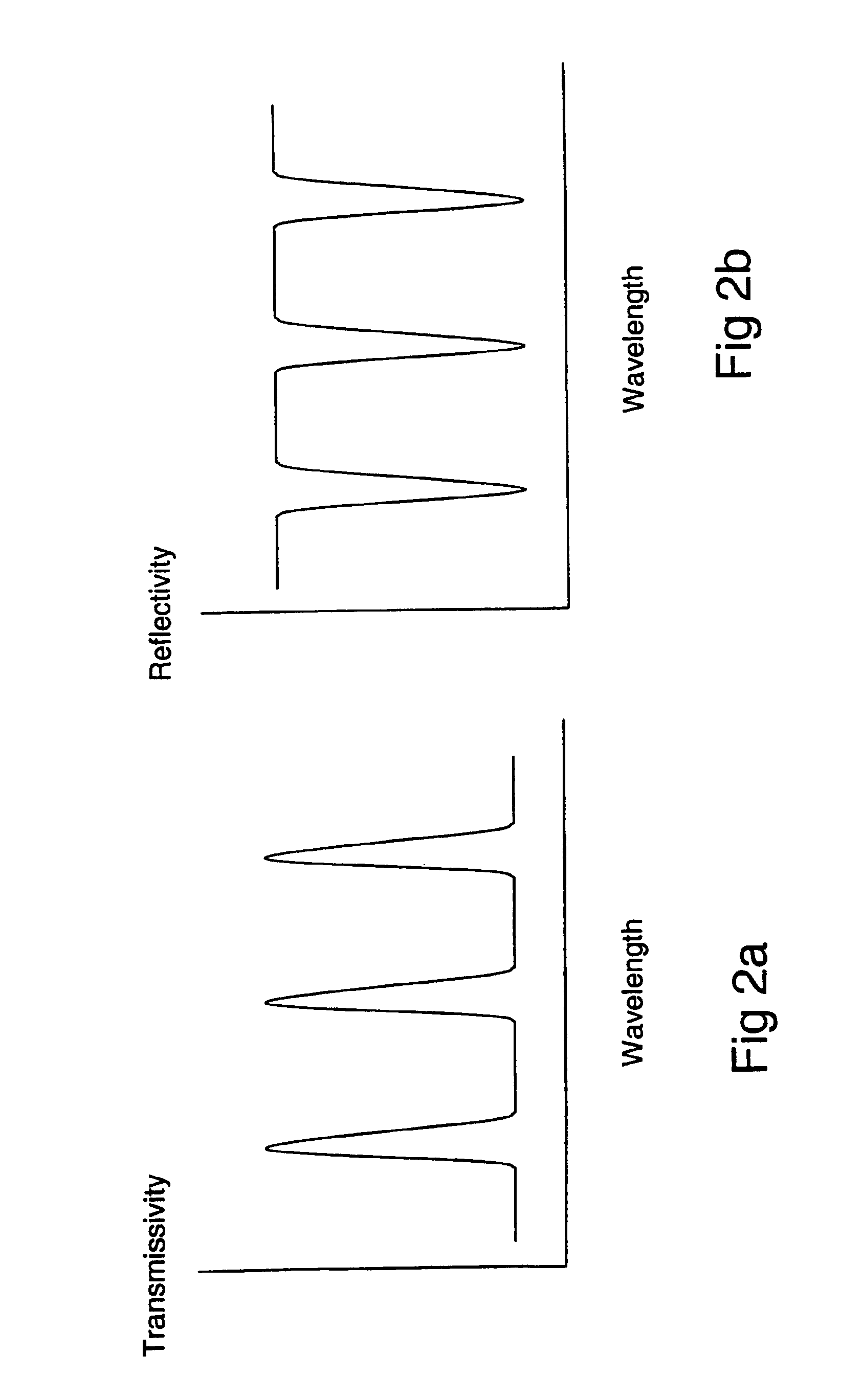
Because the reflection spectrum of an etalon does not provide a narrow bandpass filter, an etalon would not be expected to act as a tuning element in reflection.
The reason for this is the distortion of spatial distribution of the phase or the amplitude of the reflected beam.ii) The etalon of the patent may provide some additional narrowing of the laser emission spectrum (in addition to that due to the grating), but this is only possible for very low finesse of the etalon, such that the reflection spectral dependence is a sinusoidal function with a low peak value.

Method used


Image

  • Laser with reflective etalon tuning element
  • Laser with reflective etalon tuning element
  • Laser with reflective etalon tuning element

Examples


Embodiment Construction

includes passages that are chiefly or exclusively concerned with particular parts or aspects of the invention. It is to be understood that this is for clarity and convenience, that a particular feature may be relevant in more than just the passage in which it is disclosed, and that the disclosure herein includes all the appropriate combinations of information found in the different passages. Similarly, although the various figures and descriptions herein relate to specific embodiments of the invention, it is to be understood that where a specific feature is disclosed in the context of a particular figure or embodiment, such feature can also be used, to the extent appropriate, in the context of another figure or embodiment, in combination with another feature, or in the invention in general. Further, while the present invention has been particularly described in terms of certain preferred embodiments, the invention is not limited to such preferred embodiments. Rather, the scope of th...


PUM

PropertyMeasurementUnit
frequencyaaaaaaaaaa
frequencyaaaaaaaaaa
angleaaaaaaaaaa

Abstract

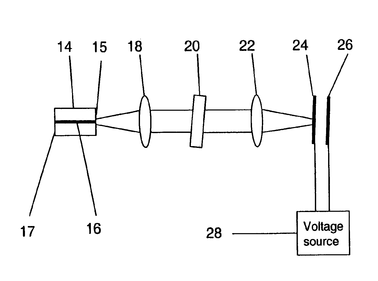
A tunable laser and laser tuning method based on the use of a tunable etalon in reflection as a mirror within a laser cavity and forming an end reflective surface thereof. The laser emission wavelength is not necessarily at a wavelength of peak etalon reflectivity. A preferred embodiment makes use of a microelectromechanical etalon to tune an external cavity semiconductor.

Description

CROSS-REFERENCE TO RELATED APPLICATIONS[0001]This application is a continuation-in-part of application Ser. No. 10 / 231,647, filed Aug. 29, 2002, now abandoned, the disclosure of which is incorporated herein by this reference.FIELD OF INVENTION[0002]This invention relates to tunable lasers and to a method of tuning lasers using an etalon in reflection.BACK GROUND OF THE INVENTION[0003]A laser consists of a pumped gain medium placed within an optical resonator.[0004]The pumped gain medium provides optical amplification, and the optical resonator provides optical feedback, such that light circulates within the optical resonator and is repeatedly amplified by the gain medium. Frequently the optical resonator is referred to as the laser cavity. Various pumps are known, the most common being optical pumps and electrical pumps.[0005]If the round trip loss within the optical resonator is less than the round trip gain provided by the gain element, the optical power increases on each round tr...

Claims


Application Information

Patent Timeline
Patent Type & Authority Patents(United States)
IPC IPC(8): G02F1/35G02F1/37H01S5/14
CPCG02F1/3501G02F1/37H01S5/141G02F1/3544G02F2001/3503G02F2201/17H01S5/142G02F1/3503
Inventor XIE, JINCHUNKATCHANOV, ALEXANDREPALDUS, BARBARA
Owner PICARRO
Learn More