
Method and system for automatically deriving stippling stitch designs in embroidery patterns

a technology of automatic derivation and embroidery pattern, applied in the field of embroidery patterns, can solve the problems of inability to create self-generating embroidery design patterns, limited use of fractal geometry for self-generating patterns, and difficulty in applying automatically generated stippling to embroidery fabrics of machinery, etc., to achieve accurate, reliable, and convenient to use

Active Publication Date: 2005-11-22
TAJIMA SOFTWARE SOLUTIONS INC
View PDF2 Cites 53 Cited by
  • Summary
  • Abstract
  • Description
  • Claims
  • Application Information

AI Technical Summary

Benefits of technology

[0017]As used herein, “determine,”“determination,”“derive,”“deriving,”“generate,”“generating” and the like should be understood broadly and refer to all aspects of determining (e.g., developing, deciding upon, establishing) data or information related to an embroidery design pattern. The present invention provides systems and methods that are accur

Problems solved by technology

However, these prior art systems do not create a self-generating embroidery design pattern based on fractal geometry where the design conforms to an area defined by an outline boundary, especially one which may be an asymmetrical or irregular polygon shape.
However, the use of fractal geometry for self-generating patterns is limited by the ability to calculate and apply the fractal shape to an area within a given outline boundary.
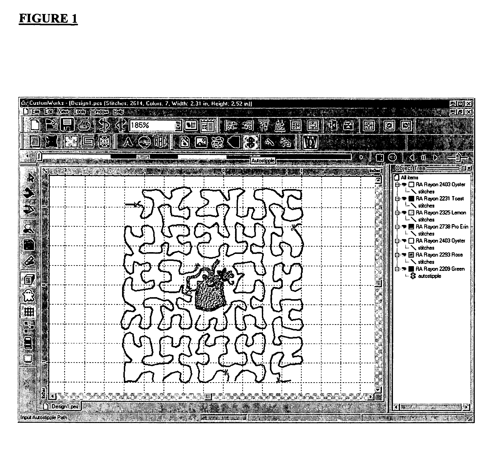
The intermittent nature of the stippling and the desire that it be relatively uniformly applied over the area, contrasting raised areas separated by the stippling stitches, distinguish this type of stitching from fill stitching or border stitching, and its seemingly random nature, and curved pattern, make application of automatically generated stippling in machinery embroidered fabrics difficult.
Yet, the initial manual manipulation requires significant training and experience to arrive at a visually appealing stippling effect.
For home embroidery program users this provides a potential drawback in computer based home embroidering systems in that no reliable computer generated pattern could adequately reproduce a desired stippling effect.
The interest in reproducing more complicated and irregular embroidery patterns and designs automatically, while achieving levels of quality formerly restricted to manually created patterns, points out the limitations in using automatically generated fractal shapes to prepare the stippling patterns.

Method used


Image

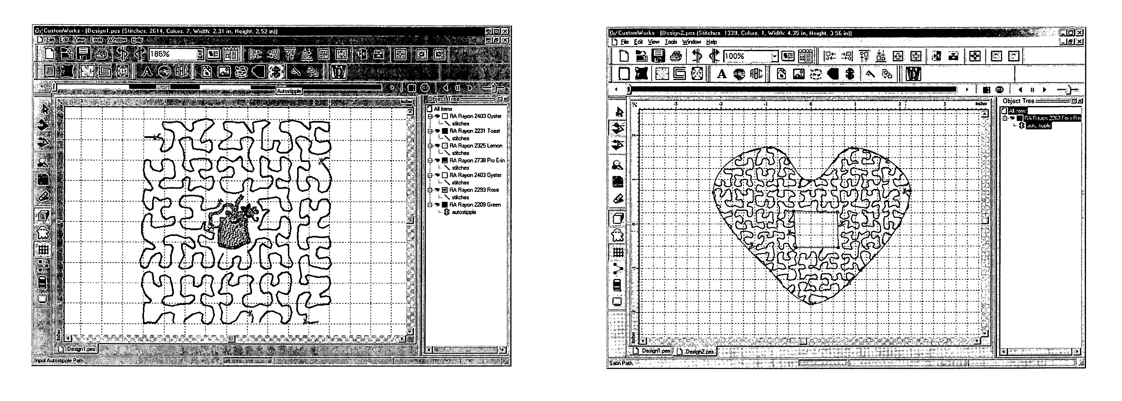
  • Method and system for automatically deriving stippling stitch designs in embroidery patterns
  • Method and system for automatically deriving stippling stitch designs in embroidery patterns
  • Method and system for automatically deriving stippling stitch designs in embroidery patterns

Examples


Embodiment Construction

[0018]The present invention relates to a method and system for creating self-generating embroidery design patterns, preferably stippling patterns, within a pre-determined surface area having an outline boundary defining an asymmetrical polygon shape or region of the surface.

[0019]“Surface” or “surface area”, as used herein, encompasses those surfaces digitally or otherwise represented on a coordinate or caretsian based graphical user interface, such as a computer monitor, or other electronic screen display, for instance, one used to generate stitch segment data that would be used by an embroidery machine to apply a design to an embroidery workpiece or surface. Similarly, “outline boundary” or “boundary” encompasses a line, line segment or segments, stitch region or spatial limitation used to define at least a portion of the surface or surface area, which also may be digitally or otherwise represented on a coordinate or cartesian based graphical user interface, such as a computer mon...


PUM


Abstract

The invention pertains to a method of applying a stippling stitch design to an area defining an asymmetrical polygon in a coordinate planar display format, involving: defining a pathway, which may be based on a fractal design, within a geometrically symmetrical boundary, the pathway comprising a single non-intersecting line; conforming the pathway to an asymmetrical polygon area substantially disposed within the geometrically symmetrical boundary; deriving a plurality of coordinate points representative of the pathway; and passing the points to a data storage medium in a pre-determined embroidery data format.

Description

PRIOR APPLICATIONS[0001]This application is based on a provisional application Ser. No. 60 / 621,340, which was filed on Oct. 22, 2004 under Express Mail Label No. EU 743 011 526 US and entitled METHOD AND SYSTEM FOR AUTOMATICALLY DERIVING STIPPLING STITCH DESIGNS IN EMBROIDERY PATTERNS.FIELD OF THE INVENTION[0002]The present invention relates to the creation of embroidery patterns for controlling embroidery machines and more particularly for creating self-generating embroidery design patterns which can be translated into embroidery machine language code for controlling such embroidery machines.BACKGROUND OF THE INVENTION[0003]Embroidery machines are generally controlled by programs. Often, a separate program is required for each embroidery design. Few systems previously available provide the ability to modify existing embroidery design programs, with such prior art systems, by way of example, varying the parameters associated with a stitch pattern design in order to control stitching...

Claims


Application Information

Patent Timeline
IPC IPC(8): D05C5/02D05C5/00G06F19/00D05B19/08
CPCD05B19/08
Inventor DIMARIDIS, CHRISTOSMAYYA, NIRANJANTRIANTAFYLLIDIS, THANASISWANG, YANCHUN
Owner TAJIMA SOFTWARE SOLUTIONS INC
Learn More