Tamping tool unit for tamping ballast

Active Publication Date: 2005-11-29
FRANZ PLASSER BAHNBAUMASCHINEN IND GMBH
View PDF4 Cites 5 Cited by
  • Summary
  • Abstract
  • Description
  • Claims
  • Application Information

AI Technical Summary

Benefits of technology

[0008]This enables the tamping tool unit to be retrofitted simply and in a minimum of time by displacing the tamping pick or its carrier in the longitudinal direction of the tamping tool unit frame along the guide, and then fixing it on the tamping tool lever in the displ

Problems solved by technology

If, for instance, a track to be tamped changes from wooden to concrete ties, the resultant c

Method used


Image

  • Tamping tool unit for tamping ballast
  • Tamping tool unit for tamping ballast
  • Tamping tool unit for tamping ballast

Examples


Example

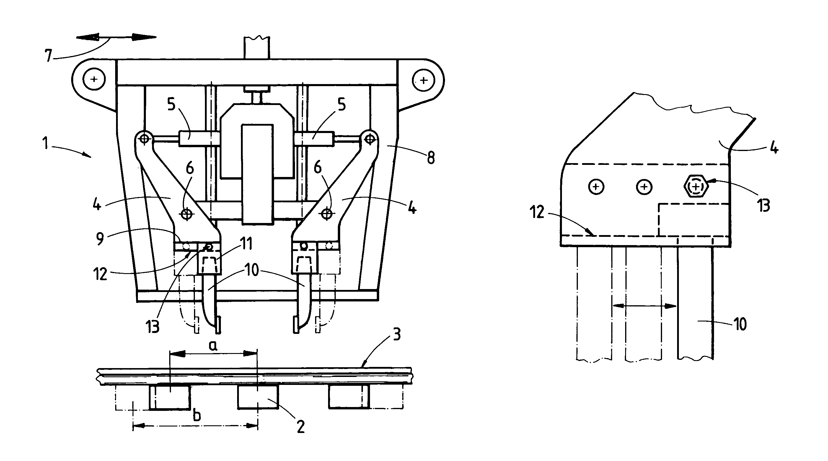
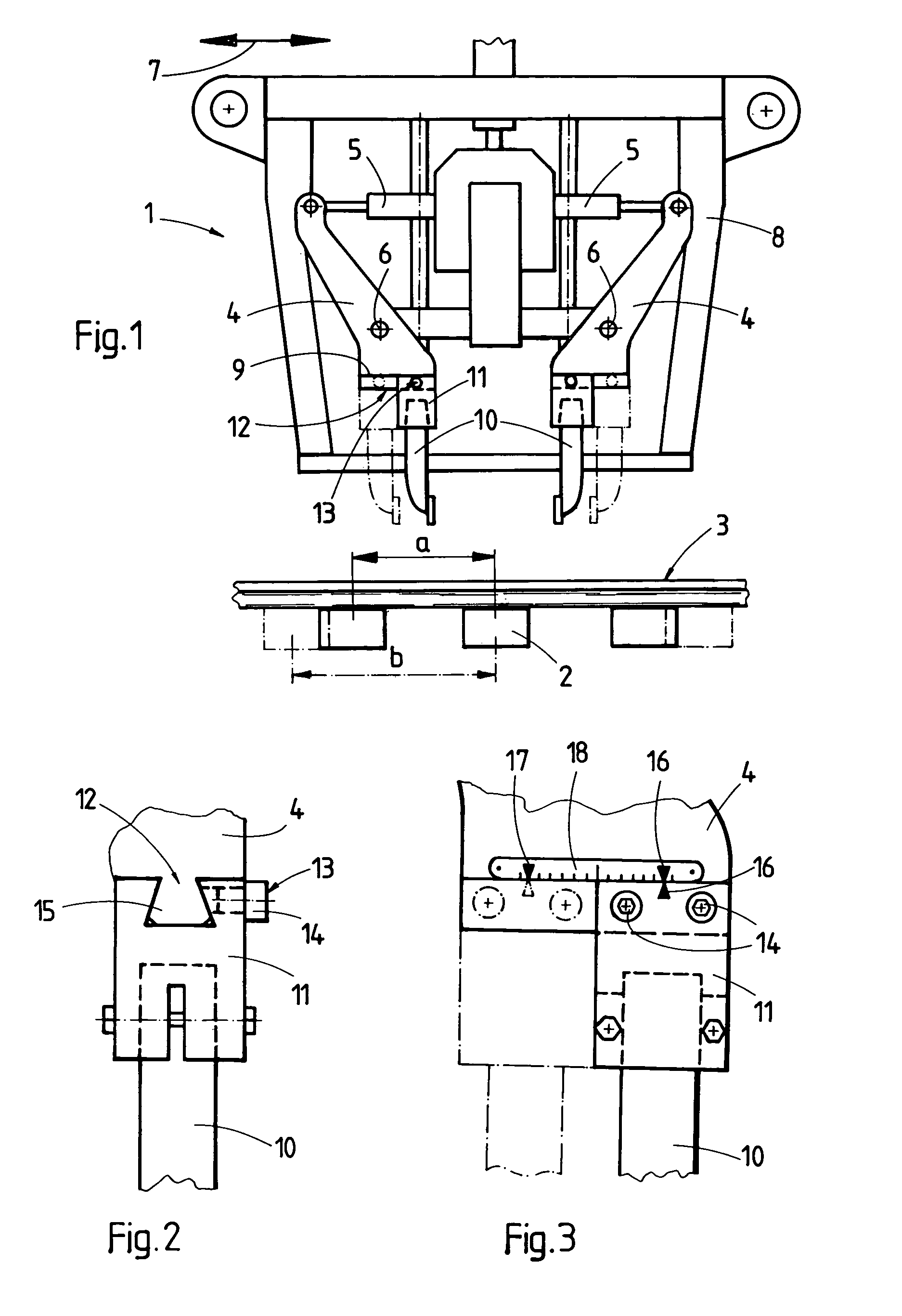
[0013]FIG. 1 illustrates tamping tool unit 1 for tamping ballast under a respective one of a succession of ties 2 of railroad track 3. The tamping tool unit comprises frame 8 extending in a longitudinal direction indicated by arrow 7, and a pair of tamping tool levers 4 mounted on frame 8 for pivoting about pivot axes 6 in a plane extending in the longitudinal direction. Each pivot axis extends in the longitudinal direction of ties 2. A reciprocating drive 5 is connected to each tamping tool lever 4 for pivoting the tamping tool lever, and tamping pick 10 is provided at lower end 9 of each tamping tool lever. Guide 12 on at least one of the tamping tool levers 4 is provided for displacing tamping pick 10 in a direction extending perpendicularly to pivot axis 6. Fixing device 13 is provided for fixing tamping pick 10 on lower tamping tool lever end 9.

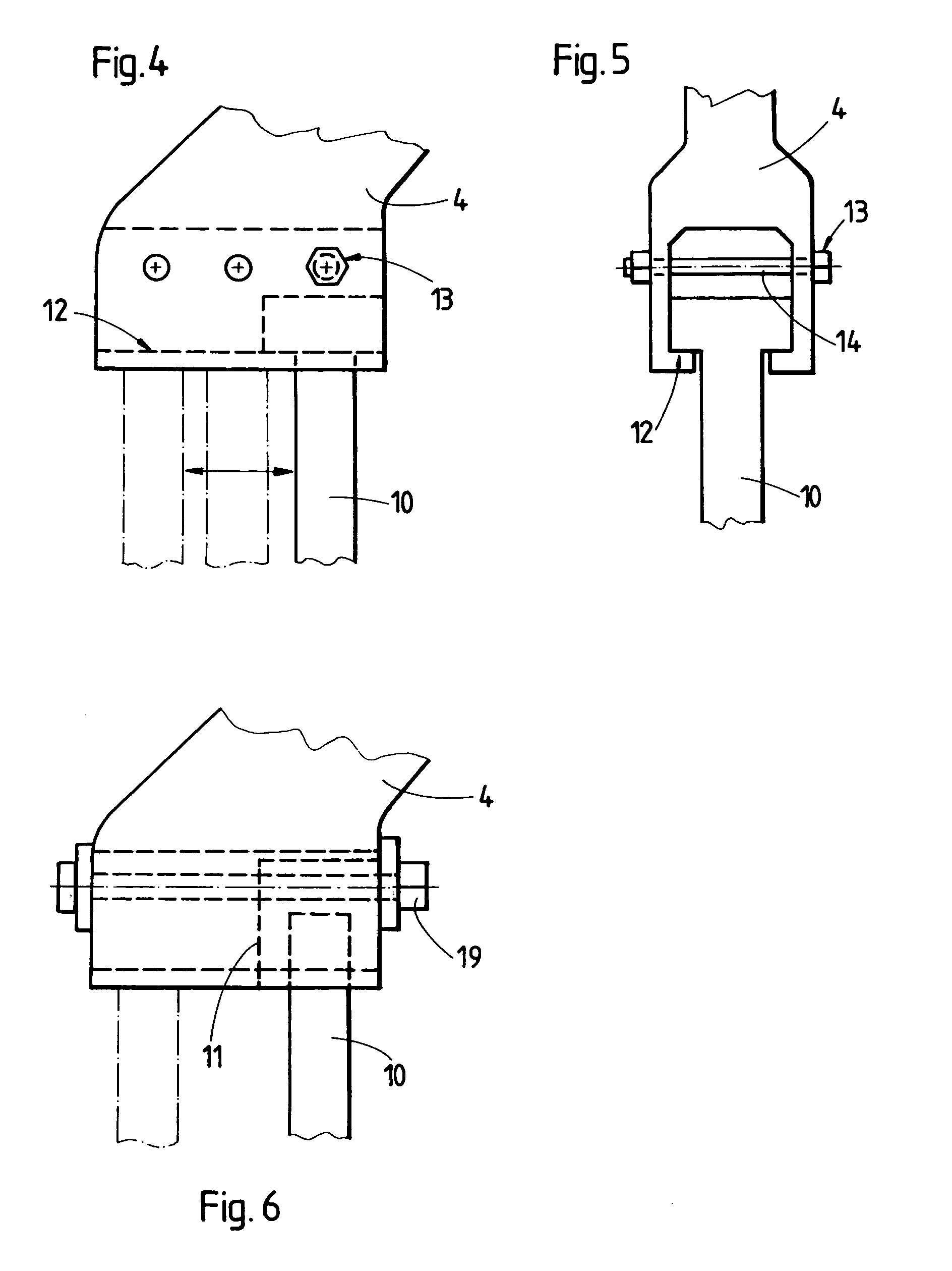
[0014]As shown in FIGS. 4 and 5, a specially designed tamping pick 10 may be guided directly in guide 12 at end 9 of tamping tool lever...


PUM


Abstract

A tamping tool unit for tamping ballast under a respective one of a succession of ties of a railroad track comprises a frame extending in a longitudinal direction, a pair of tamping tool levers mounted on the frame for pivoting about pivot axes in a plane extending in the longitudinal direction, a reciprocating drive connected to each tamping tool lever for pivoting the tamping tool lever, and a tamping pick at a lower end of each tamping tool lever. A guide on at least one of the tamping tool levers is provided for displacing the tamping pick in a direction extending perpendicularly to the pivot axis of the at least one tamping tool lever, and a fixing device is provided for fixing the tamping pick on the lower tamping tool lever end.

Description

BACKGROUND OF THE INVENTION[0001]1. Field of the Invention[0002]The present invention relates to a tamping tool unit for tamping ballast under a respective one of successive ties of a railroad track, which comprises a frame extending in a frame extending in a longitudinal direction, a pair of tamping tool levers mounted on the frame for pivoting about a pivot axis in a plane extending in the longitudinal direction, a reciprocating drive connected to each tamping tool lever for pivoting the tamping tool lever, and a tamping pick at a lower end of each tamping tool lever.[0003]2. Description of the Prior Art[0004]Such tamping tool units are well known, and U.S. Pat. No. 4,576,095 discloses such a tamping tool unit wherein the opening width of a pair of reciprocating tamping tool levers may be selectively varied, which may be necessary, for example, if a double tie is to be tamped by the pair of reciprocating tamping tool levers. For this purpose, a stop pivotal into engagement with th...

Claims


Application Information

Patent Timeline
IPC IPC(8): E01B1/00E01B27/12E01B27/16E01B37/00
CPCE01B27/16
Inventor THEURER, JOSEF
Owner FRANZ PLASSER BAHNBAUMASCHINEN IND GMBH
Why Eureka
Try Eureka