Apparatus and methods for conveying objects

a technology of objects and apparatus, applied in the direction of rotary conveyors, conveyor parts, transportation and packaging, etc., can solve the problems of inconsistent or inefficient diverting of objects, slippage of rollers, etc., and achieve the effect of reducing the slippage of the first roller

Inactive Publication Date: 2005-11-29
LAITRAM LLC
View PDF6 Cites 91 Cited by
  • Summary
  • Abstract
  • Description
  • Claims
  • Application Information

AI Technical Summary

Benefits of technology

[0005]In one embodiment, a method comprises driving a modular conveyor belt in a direction of belt travel; rotating a plurality of first rollers disposed into the modular conveyor belt in a manner in which slippage of the first rollers is reduced; and conveying objects on the modular conveyor belt using the rotating first rollers.

Problems solved by technology

The use of the wear strips to rotate the rollers causes the rollers to slip in that the rollers intermittently slide along the wear strips.
Such slippage is undesirable in that it results in inconsistent or inefficient diverting of the objects.

Method used


Image

  • Apparatus and methods for conveying objects
  • Apparatus and methods for conveying objects
  • Apparatus and methods for conveying objects

Examples


Embodiment Construction

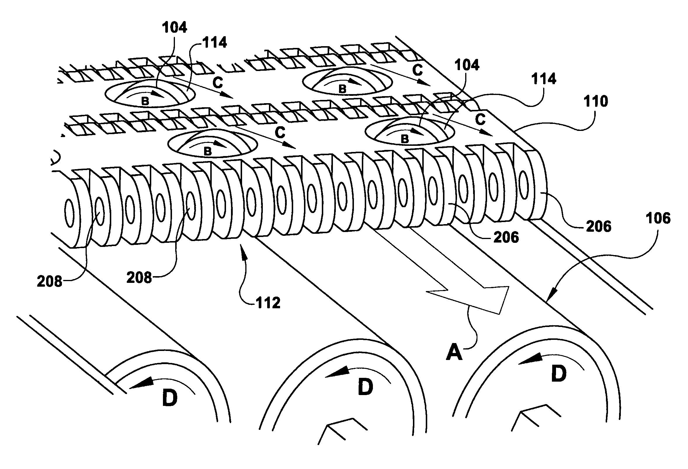
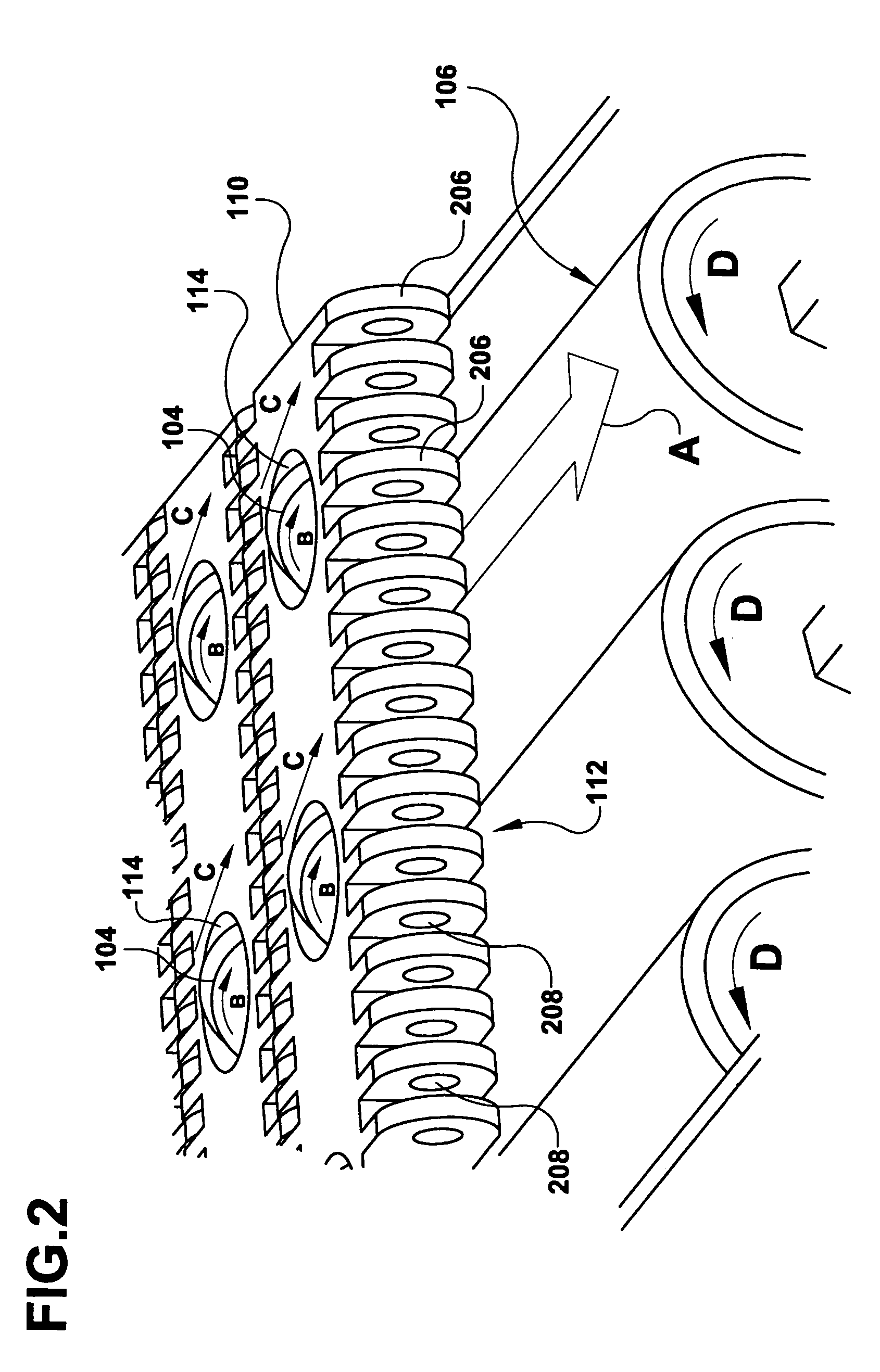
[0014]Disclosed are conveyors and methods for conveying objects that reduce slippage of conveyor rollers. Due to that reduced slippage, the conveyors more effectively divert objects on the conveyor belt. In some embodiments, the conveyor includes first rollers disposed in the conveyor belt and at least one second roller located underneath the conveyor belt that can rotate in a direction transverse to the direction of travel of the conveyor belt. As the conveyor belt travels along the second roller, the second roller operatively couples with the first rollers causing the first rollers and the second roller to rotate. Because of the rotation of the second roller, the first rollers rotate with reduced slippage.

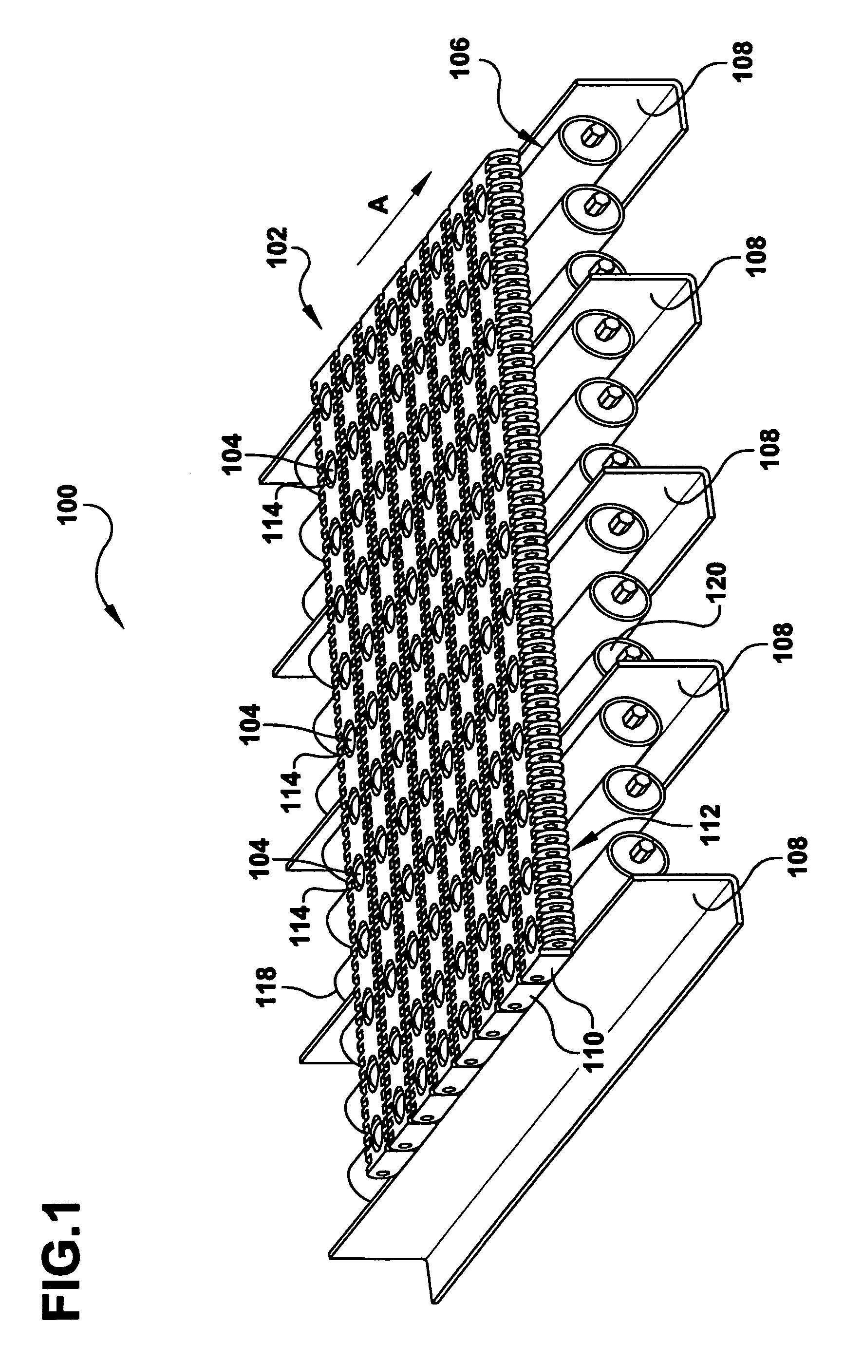
[0015]Referring now in more detail to the figures in which like referenced numerals identifying corresponding parts, FIG. 1 illustrates a perspective view of an embodiment of a section of a conveyor 100 in which a plurality of first rollers 104 are disposed in a conveyor belt 102...


PUM


Abstract

Disclosed are conveyors and methods for making the conveyors. In one embodiment, a conveyor comprises a modular conveyor belt that includes a plurality of mat-top chains having a plurality of cavities and a plurality of first rollers disposed in the cavities of the mat-top chains. The conveyor further includes at least one second roller that operatively couples to the first rollers such that the first rollers rotate as the conveyor belt travels along the second roller. The invention can also be construed as providing the method for conveying objects. The method can comprise the steps of driving a modular conveyor belt in a direction of belt travel; rotating a plurality of first rollers disposed into the modular conveyor belt in a manner in which slippage of the first rollers is reduced; and conveying objects on the modular conveyor belt using the rotating first rollers.

Description

TECHNICAL FIELD[0001]The invention generally relates to power-driven conveyors.DESCRIPTION OF THE RELATED ART[0002]Switch conveyors have been developed that include a modular conveyor belt that includes rows of rollers. The rollers are disposed in the modular conveyor belt and are angled relative to the direction of travel of the belt such that they can laterally divert objects placed on the belt. The conveyor includes fixed longitudinal wear strips that are located below the conveyor belt. As the conveyor belt travels, the rollers travel along the longitudinal wear strips causing the rollers to rotate for the purpose of diverting objects.[0003]The use of the wear strips to rotate the rollers causes the rollers to slip in that the rollers intermittently slide along the wear strips. Such slippage is undesirable in that it results in inconsistent or inefficient diverting of the objects.SUMMARY[0004]Disclosed are conveyors and methods for conveying objects. In one embodiment, a conveyo...

Claims


Application Information

Patent Timeline
Patent Type & Authority Patents(United States)
IPC IPC(8): B65G17/08B65G17/24B65G17/40B65G47/53
CPCB65G17/08B65G17/24B65G17/40B65G47/34B65G2201/02
Inventor FOURNEY, MATTHEW L.
Owner LAITRAM LLC
Why Eureka
Try Eureka