Dental implant tool with attachment feature

a technology of dental implants and tools, applied in dental tools, dental surgery, medical science, etc., can solve the problems of difficult attachment of drill bushings to stents, and achieve the effect of improving the stability and stability of drilling bushings

Inactive Publication Date: 2005-12-06
LEO J MARLIN
View PDF19 Cites 94 Cited by
  • Summary
  • Abstract
  • Description
  • Claims
  • Application Information

AI Technical Summary

Benefits of technology

[0012]Another object of some embodiments is to provide the bushing holder with a

Problems solved by technology

A drill bushing, unfortunately, can be difficult to attach to a stent, particularly if the drill b

Method used


Image

  • Dental implant tool with attachment feature
  • Dental implant tool with attachment feature
  • Dental implant tool with attachment feature

Examples


Embodiment Construction

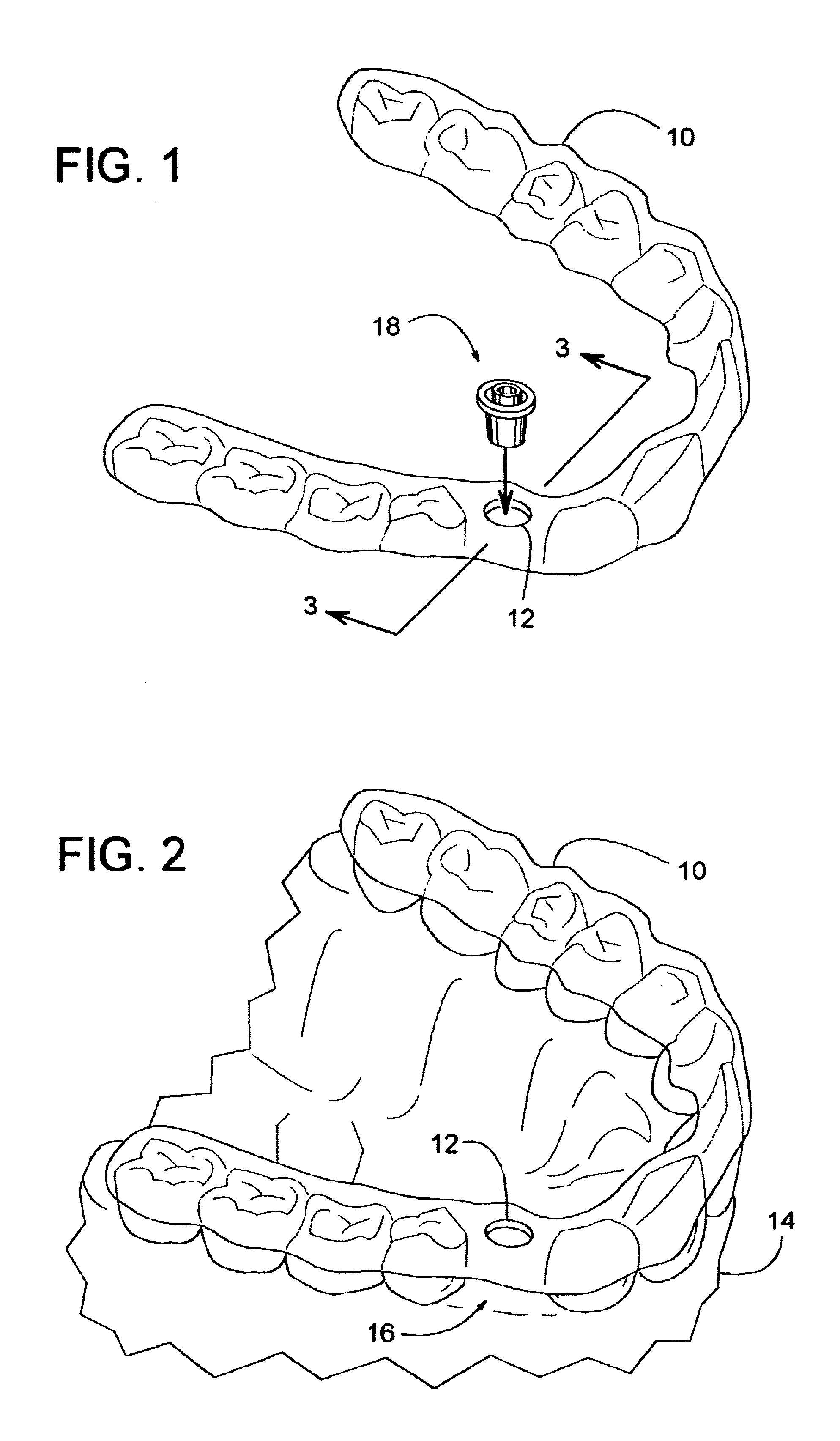
[0025]FIG. 1 shows a dental stent 10 having a hole or bore 12, and FIG. 2 shows stent 10 attached to a patient's jaw 14 (upper or lower jaw). The term, “jaw” refers to that part of a patient's body that comprises one or more of the following: teeth, gums, and / or jawbone (upper or lower). Stent 10 is a conventional surgical dental stent that can be produced in various ways that are well known to those skilled in the art. Stent 10 can be hollow or solid in an area 16 of the missing tooth. Bore 12, which is in area 16 of the missing tooth, can be created in stent 10 by various methods including, but not limited to, drilling, punching, cutting, etc.

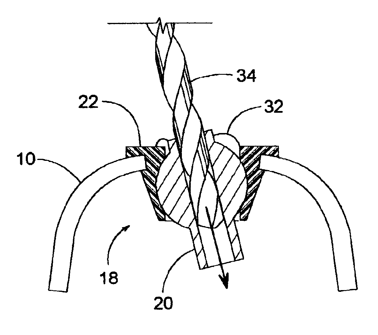
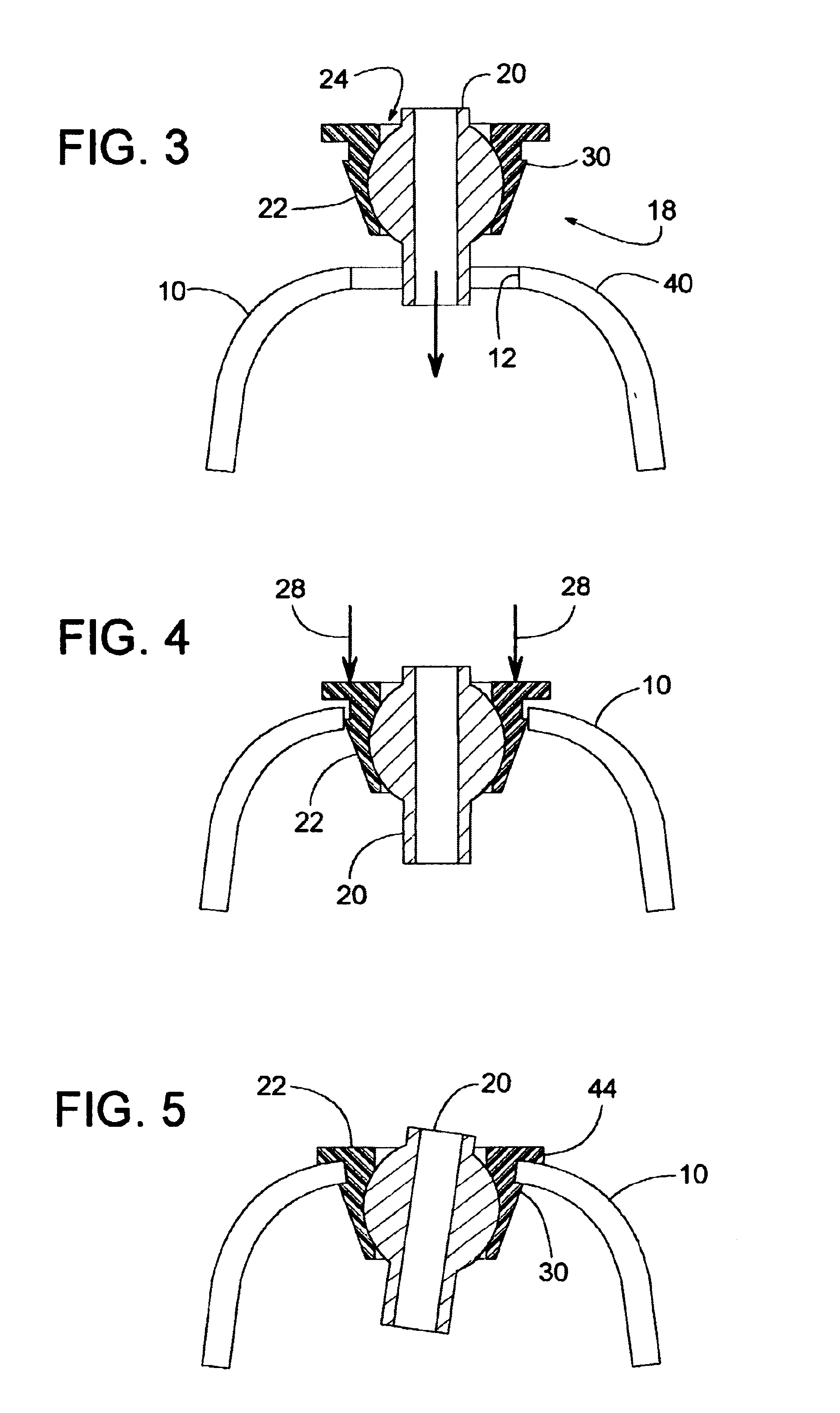
[0026]FIGS. 1 and 3 show a dental tool 18 being inserted into bore 12. Dental tool 18 comprises a drill bushing 20 attached to a bushing holder 22. A ball-and-socket joint 24 enables drill bushing 20 to pivot relative to bushing holder 22. More specifically, bushing 22 can pivot to set the angle of a drill bit's trajectory. To prevent bushing...


PUM


Abstract

A dental tool for guiding a drill bit during a dental implant procedure includes a pivotal drill bushing attached to a bushing holder. The bushing holder, in turn, is attached to a surgical dental stent that fits a patient's jaw. The bushing holder attaches to the stent by extending into a hole or bore of the stent. In some cases, the bushing holder snaps into the hole.

Description

BACKGROUND OF THE INVENTION[0001]1. Field of the Invention[0002]The subject invention generally pertains to dental implants and more specifically to a tool for installing them.[0003]2. Description of Related Art[0004]Various dental implant methods and devices have been developed for replacing one or more missing teeth in a person's jaw with prosthetic teeth. For many prosthetic teeth, a final product comprises three basic components: an implant, an abutment, and a crown. The crown is the exposed portion of the prosthesis that resembles one or more teeth. The implant is an anchor that becomes attached to the jawbone, and the abutment couples the crown to the implant.[0005]To install the implant, a hole is usually drilled into the patient's jawbone, and the implant is inserted into the hole.[0006]A drill bushing attached to a stent can be used to help guide the drill bit, as disclosed in PCT Publication WO 99 / 26540 and U.S. Pat. Nos. 5,015,183; 5,133,660; 5,718,579. A drill bushing, u...

Claims


Application Information

Patent Timeline
IPC IPC(8): A61C1/08
CPCA61C1/084
Inventor HARTER, ROBERT J.
Owner LEO J MARLIN
Why Eureka
Try Eureka