Multi-directional internal distraction osteogenesis device

a multi-directional, osteogenesis technology, applied in the field of bone distractor devices, can solve problems such as the generation or distraction of linear bone segments

Inactive Publication Date: 2005-12-06
NEW YORK UNIV
View PDF5 Cites 108 Cited by
  • Summary
  • Abstract
  • Description
  • Claims
  • Application Information

AI Technical Summary

Benefits of technology

[0004]A bone distractor for distracting bone tissue includes a first bone attachment portion, a second bone attachment portion, and a linkage connecting the first bone attachment portion with the second bone attachment portion. Th

Problems solved by technology

The transport bone segment is attached to a linear device that allows the transport bone segment to

Method used


Image

  • Multi-directional internal distraction osteogenesis device
  • Multi-directional internal distraction osteogenesis device
  • Multi-directional internal distraction osteogenesis device

Examples


Embodiment Construction

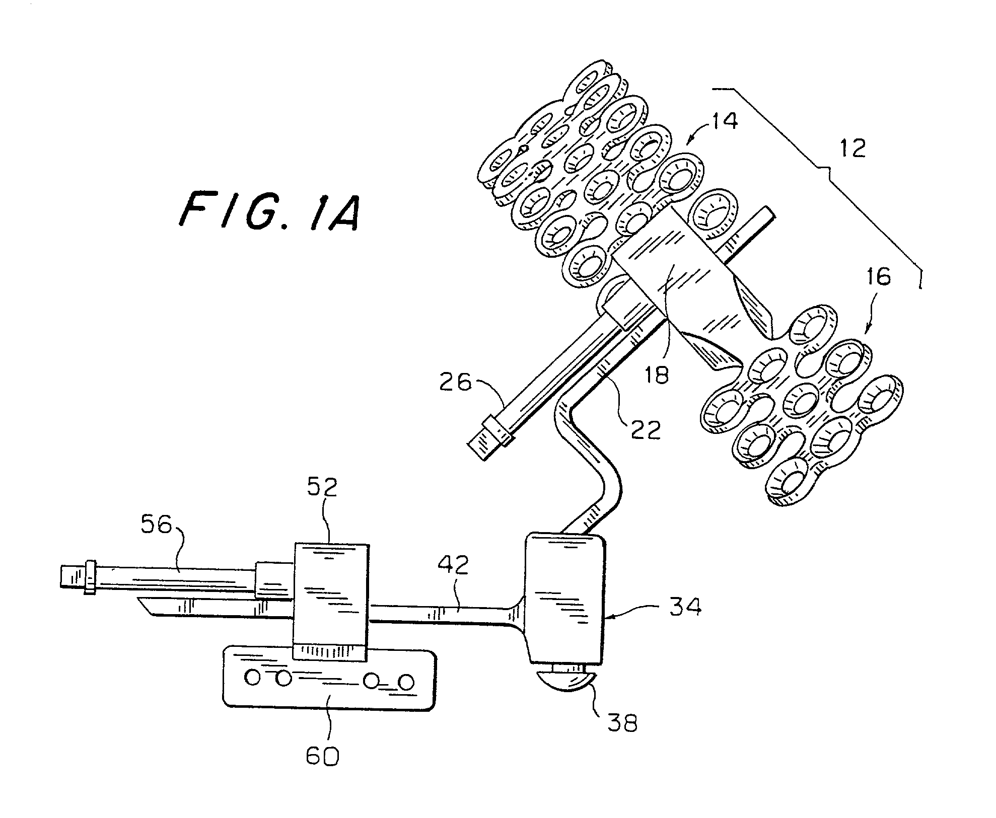
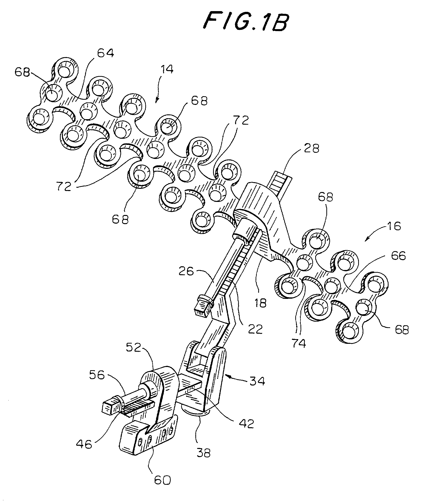
[0020]A first preferred embodiment of the invention is illustrated in FIGS. 1A–1D, which will be described together.

[0021]This embodiment includes an upper plate 12 composed of two wings 14 and 16. Plate 12 is secured to, and forms a unit with, an upper housing 18. All of the components of the device illustrated in FIGS. 1A–1D may be made of metal and wings 14 and 16 and housing 18 may be formed as a single cast unit, or wings 14 and 16 may be formed separately from housing 18 then welded to the side of walls of housing 18. An upper drive track 22 extends through a passage in housing 18. This passage may be formed directly in the cast unit constituting housing 18. A shaft 26 carries a threaded element (not visible) that also extends into the opening in housing 18. The threaded end of shaft 26 engages threading, or teeth, 28 on track 22 in such a manner that rotation of shaft 26 will produce movement of housing 18 along the length of track 22. Thus, track 22 cooperates with the threa...


PUM


Abstract

The present invention provides an improved orthopedic system for the modification of the distance between the maxilla and zygoma. In a preferred embodiment, the system includes proximal and distal footplates attached to an orthopedic device. The distal footplate is attached to the zygoma, with the proximal footplate being mechanically coupled to the maxilla. This mechanical coupling is achieved either through attachment directly to the maxilla or by attachment to a construct which is then wired to the patient's teeth. The orthopedic device, which may be a distractor, allows for modification of the distance between the maxilla and zygoma. The entire system can advantageously be placed intra-orally within a patient. In a preferred embodiment, the footplates are also detachable from the orthopedic device and are composed of a bioresorbable material, such that they will be absorbed by the patient's body. Methods for using this novel orthopedic system are also disclosed.

Description

CROSS-REFERENCE TO RELATED APPLICATION[0001]This application claims priority rights from U.S. Provisional Application 60 / 294,640, filed Jun. 1, 2001.BACKGROUND OF THE INVENTION[0002]The present invention relates generally to a bone distractor device and more particularly, to a bone distractor device having multiple degrees of freedom.[0003]Conventional bone distractor devices utilize plates fixed to different bone areas, a transport bone segment, and a fixed bone area. The transport bone segment is attached to a linear device that allows the transport bone segment to be moved along a linear path, resulting in the generation or distraction of a linear bone segment. When a bone segment is to be distracted in other than the direction in which the distractor device is connected, the distraction device usually must be removed and reattached, requiring additional medical procedures. The present invention was developed in light of these drawbacks.BRIEF SUMMARY OF THE INVENTION[0004]A bone ...

Claims


Application Information

Patent Timeline
IPC IPC(8): A61B17/58A61B17/66
CPCA61B17/663
Inventor GRAYSON, BARRYVENDITTELLI, BRUNOMCCARTHY, JOSEPHHARROW, MATTHEWSCHUMACHER, BRIAN
Owner NEW YORK UNIV
Why Eureka
Try Eureka