Compressor discharge chamber with baffle plate

a compressor and discharge chamber technology, applied in the direction of positive displacement liquid engines, room acoustics, liquid fuel engines, etc., can solve the problems of unacceptable vibration, unfavorable compressor operation, and inability to meet the requirements of the compressor, etc., to achieve the effect of reducing the noise of the compressor

Inactive Publication Date: 2005-12-20
CARRIER CORP
View PDF6 Cites 27 Cited by
  • Summary
  • Abstract
  • Description
  • Claims
  • Application Information

AI Technical Summary

Problems solved by technology

If a single discharge chamber is utilized, there is the potential for cyclic fluctuations in the conditions within the discharge chamber.
When these two frequencies approached each other, unacceptable vibration occurred.
Also, the magnitude of fluctuation and resultant noise are undesirably high in this existing compressor.

Method used


Image

  • Compressor discharge chamber with baffle plate
  • Compressor discharge chamber with baffle plate
  • Compressor discharge chamber with baffle plate

Examples


Embodiment Construction

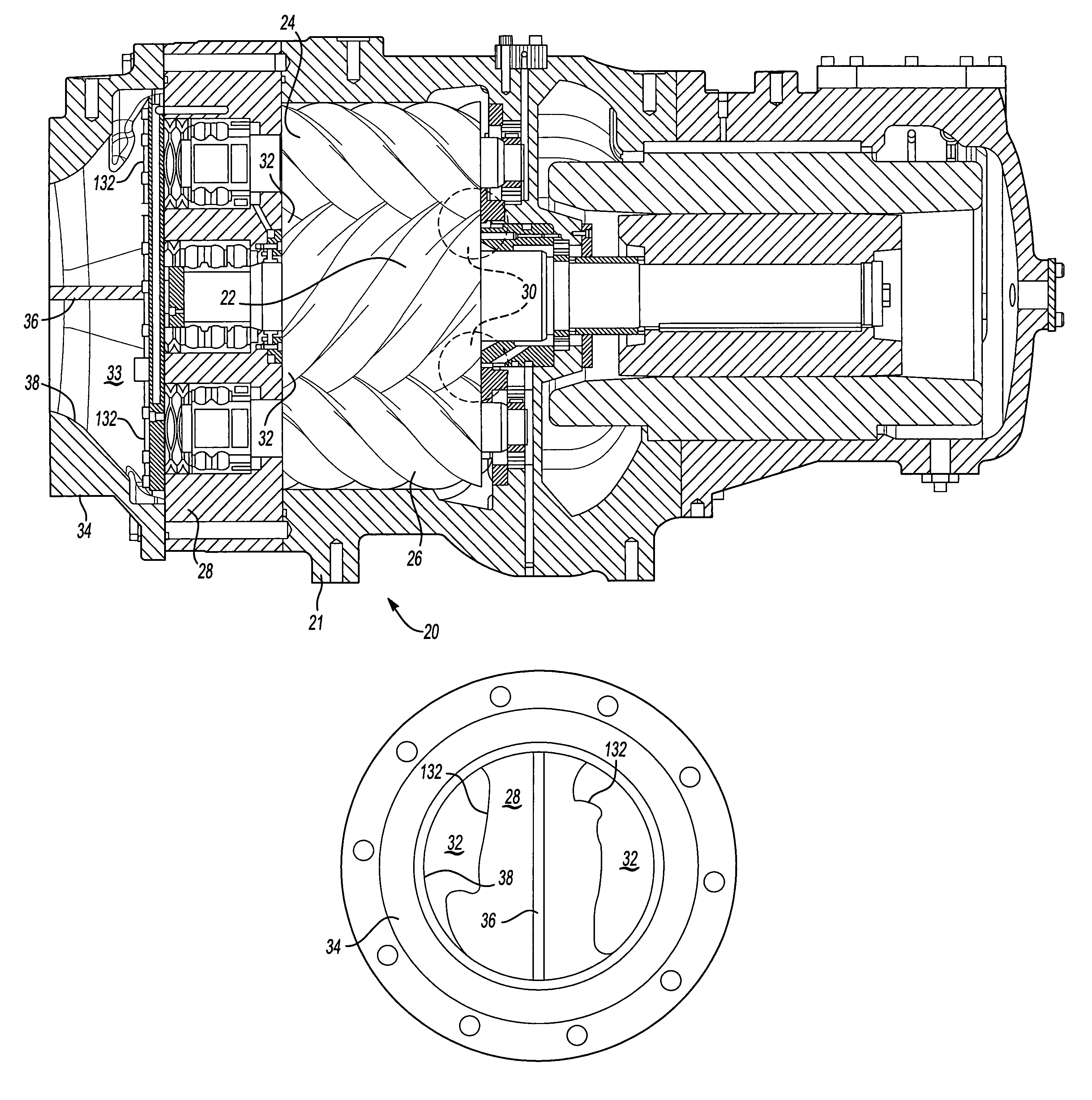
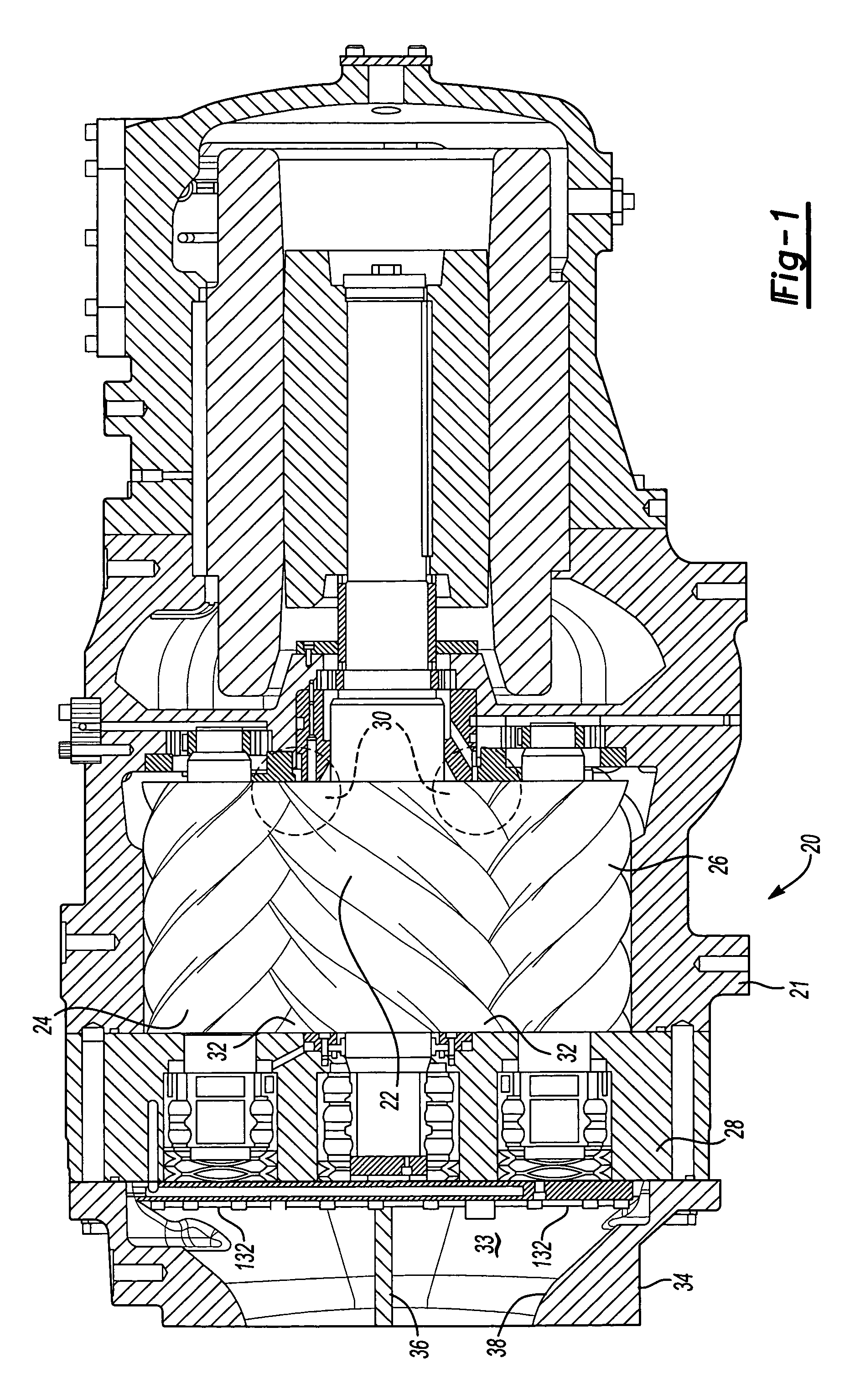
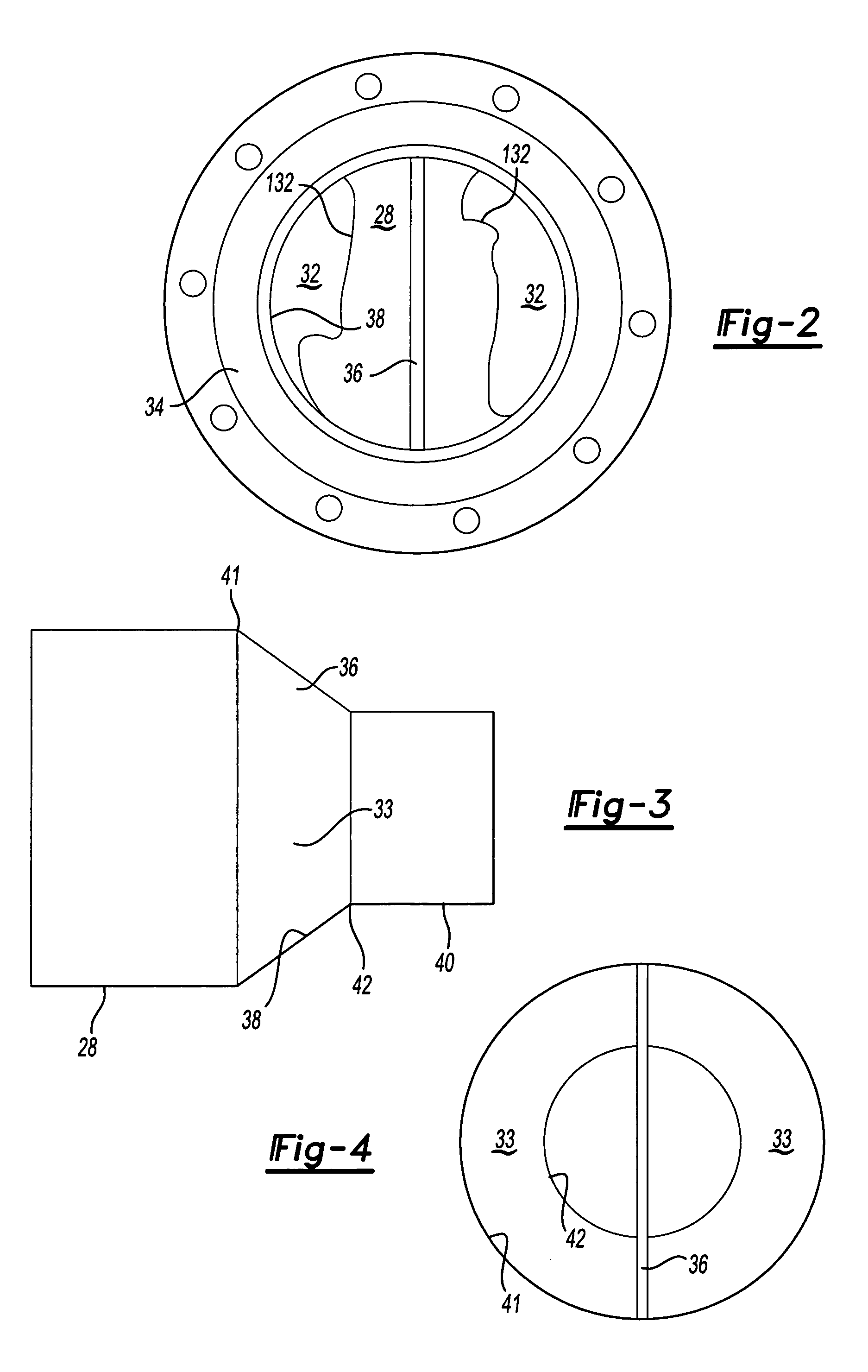
[0010]A compressor 20 is illustrated in FIG. 1 having a housing 21 receiving a central drive screw 22 and two opposed screws 24 and 26. A discharge plate 28 receives compressed refrigerant from compression chambers 32 and delivers this compressed refrigerant through discharge ports in the plate 28 (not shown in FIG. 1) to a discharge chamber 33 in an outlet housing 34. As known, refrigerant is delivered through inlet ports 30, and compressed between the screws 22 and 24 and 22 and 26 toward the discharge ports 132. As shown, a baffle plate 36 is positioned generally in the middle of the discharge chamber 33. The size of the chamber 33 necks down with the inner peripheral surface 38 of the outlet housing 34. As mentioned above, without the baffle plate 36, there has sometimes been undesirable vibration, noise and fluctuations occurring in the compressor 20. The baffle plate 36 serves to change the fluid frequency of the system such that the above-mentioned vibration will not occur du...


PUM


Abstract

A screw compressor is provided with a discharge chamber that receives alternating flows of compressed fluid from two compression chambers located on opposed sides of the screw compressor. The discharge chamber is provided with a central baffle plate separating the two flows. The baffle plate changes the fluid frequency of the system, and ensures that the fluid system will not operate at a frequency that approaches the natural frequency of the overall compressor, thus reducing undesirable vibrations. The baffle plate also reduces the magnitude of the fluctuations and the resultant noise.

Description

BACKGROUND OF THE INVENTION[0001]This application relates to the use of a baffle plate separating a compressor discharge chamber into sub-chambers, in the type of compressor having plural cyclically discharging flows.[0002]Many types of compressors are utilized to compress various fluids. In one general type of compressor, the flow of a compressed fluid from the compression chambers occurs cyclically from a plurality of compression chambers. As an example, in a screw compressor having three rotors, there are two compression sets between, with one center screw and each one of the two side screws. These sets periodically discharge a compressed refrigerant into a discharge chamber through discharge ports. The ports are on opposed sides of the discharge chamber. If a single discharge chamber is utilized, there is the potential for cyclic fluctuations in the conditions within the discharge chamber. One example of such a compression discharge structure is disclosed in U.S. Pat. No. 6,488,...

Claims


Application Information

Patent Timeline
Patent Type & Authority Patents(United States)
IPC IPC(8): F04C29/00F04C29/12
CPCF04C29/0035F04C29/068F04C29/12F04C18/165F04C2250/102Y10S181/403F04C18/16F04C29/06
Inventor DANIELS, MARK A.TETU, LEE G
Owner CARRIER CORP
Why Eureka
Try Eureka