Device retention apparatus locking assembly

a technology of device retention and locking assembly, which is applied in the direction of electric apparatus casings/cabinets/drawers, washstands, instruments, etc., can solve the problems of damage to the information handling system, difficult manipulation and installation, and laborious installation of these devices in the information handling system

Inactive Publication Date: 2005-12-27
GATEWAY
View PDF17 Cites 21 Cited by
  • Summary
  • Abstract
  • Description
  • Claims
  • Application Information

AI Technical Summary

Benefits of technology

[0009]In another aspect of the present invention, a method of retaining an electronic device in a housing includes engaging a first device side of an information handling system device against a first housing side of a housing for retaining an information handling system device. The housing includes the first housing side, a second housing side, and a third housing side, wherein the second housing side is oriented generally opposing the first housing side, and the third housing side is oriented generally perpendicular to the first housing side and the second housing side. The information handling system device includes a first device side, a second device side, and a third device side. The information handling system device is rotated about the portion of the information handling system device engaged with the housing, so that the information handling system device is secured to the first housing side, second housing side, and third housing side.

Problems solved by technology

However, the installation of these devices in the information handling system may be very labor intensive.
Typically, these screws are small, making them difficult to manipulate and install.
Additionally, because of their small size, the screws may be dropped by an assembler, possibly causing damage to the information handling system due to shorts, lodging in moving parts, and the like.
With this smaller size comes a corresponding lack of space, making it even more difficult to mount devices in an information handling system.
Further, the upgrade and repair of information handling system devices has become increasingly complicated.
This may require a significant amount of time and result in a loss of components, such as the screws and other attaching hardware.

Method used


Image

  • Device retention apparatus locking assembly
  • Device retention apparatus locking assembly
  • Device retention apparatus locking assembly

Examples


Embodiment Construction

[0030]Reference will now be made in detail to the presently preferred embodiments of the invention, examples of which are illustrated in the accompanying drawings.

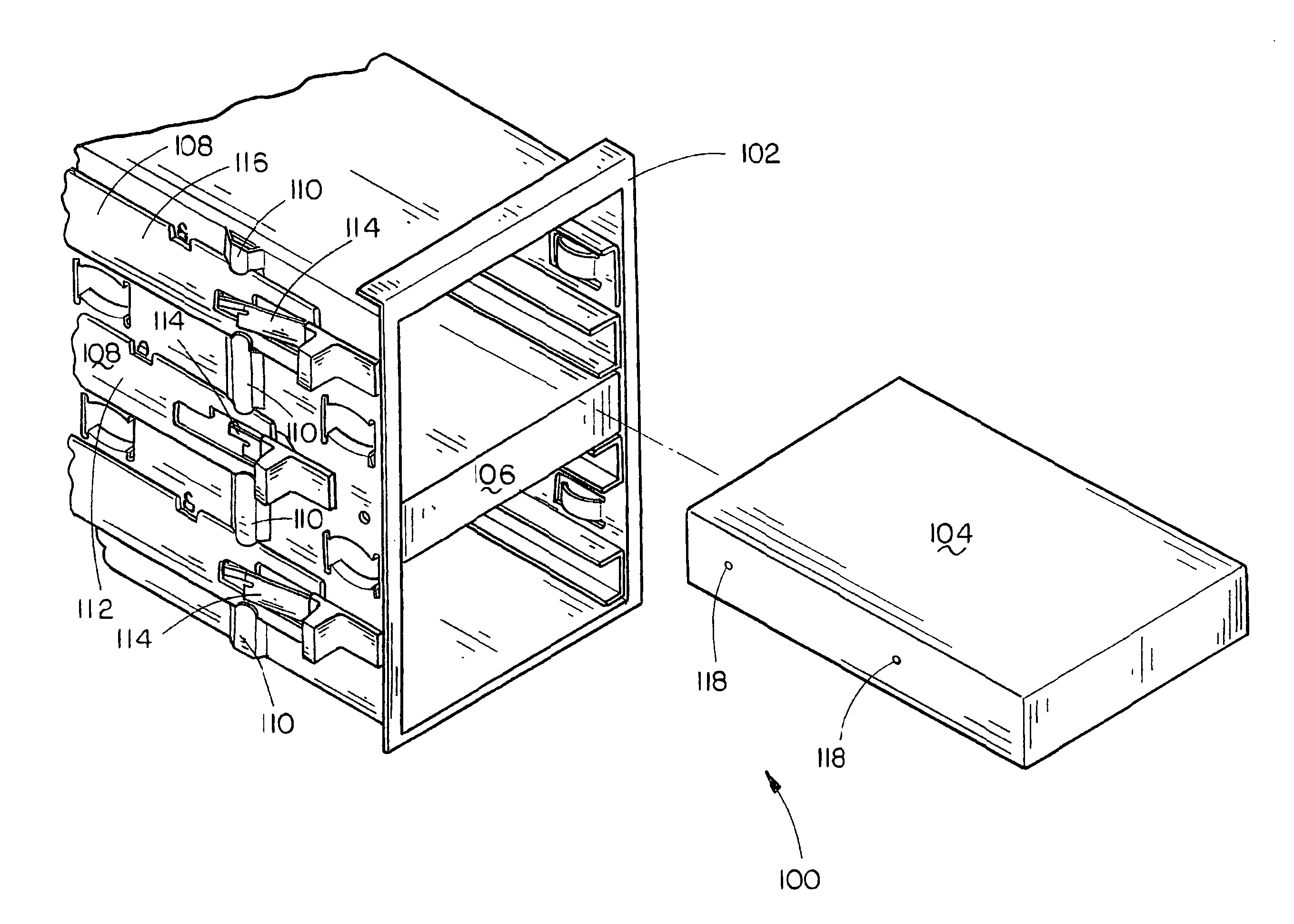
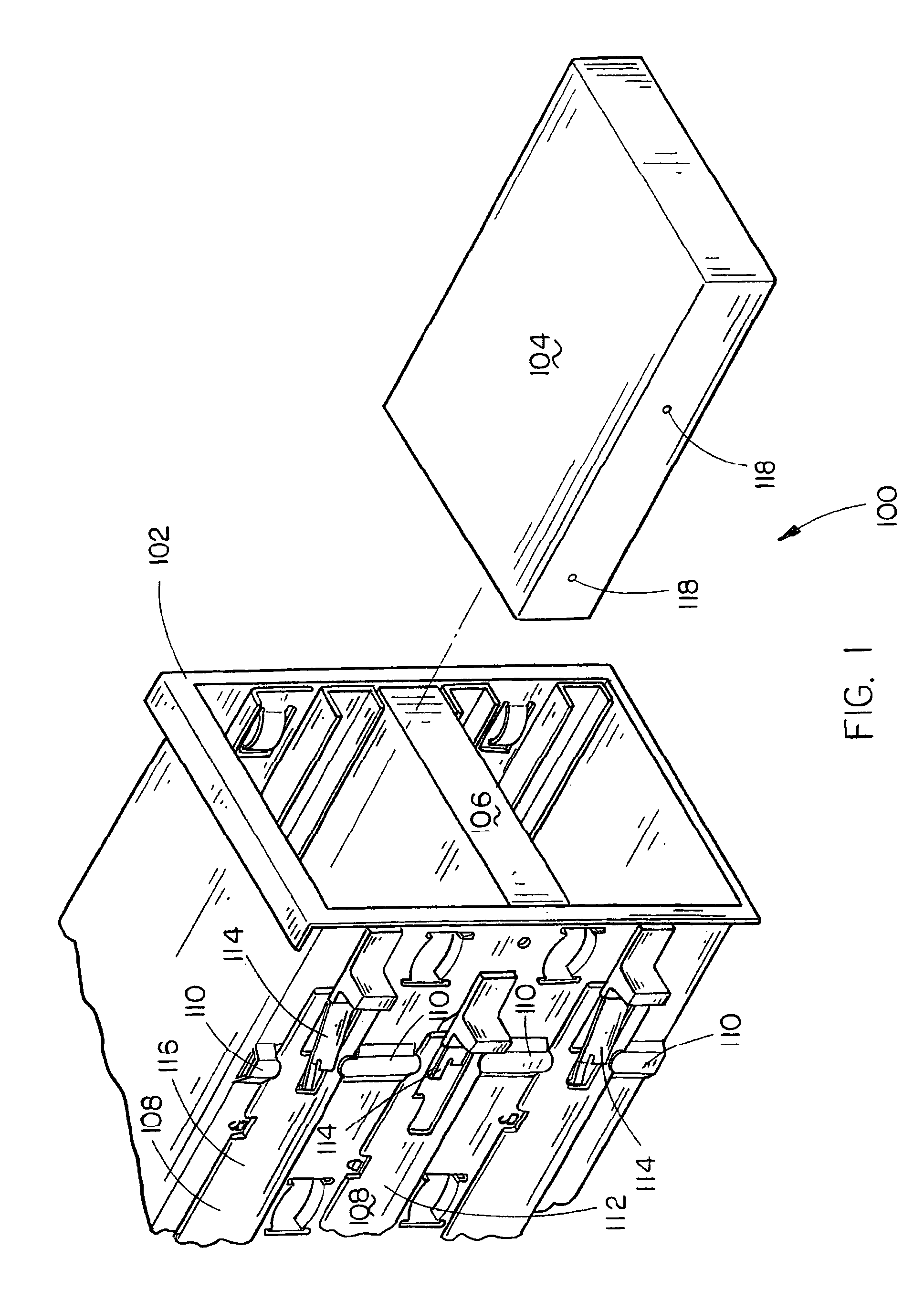
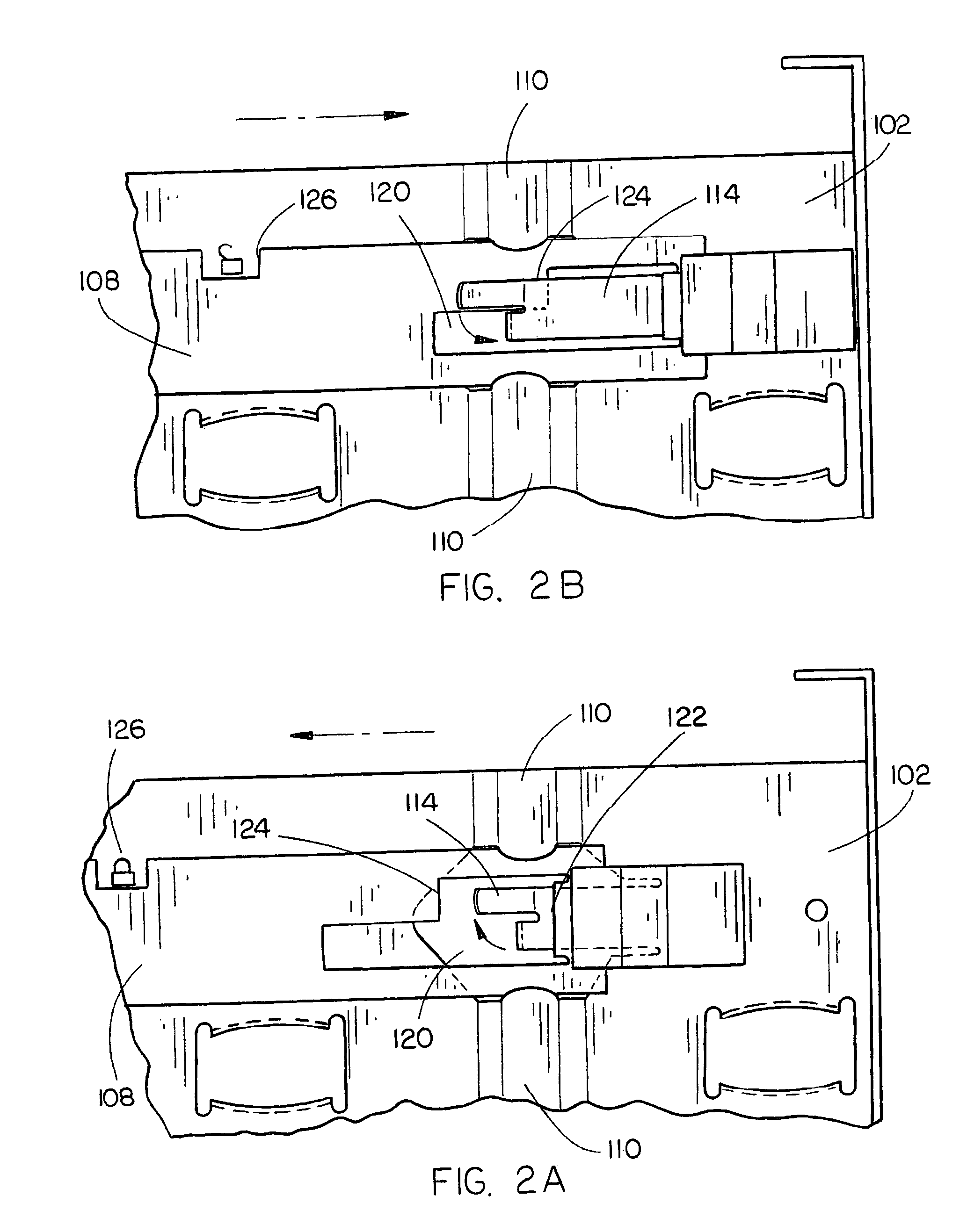
[0031]Referring generally now to FIGS. 1 through 10B, a device retention apparatus in accordance with exemplary embodiments of the present invention is described. Information handling systems such as desktop computers, tower systems, convergence systems, servers, and the like may be complicated to manufacture and update. To install and remove information handling system devices, such as compact disc read-only memory (CD-ROM) drives, digital versatile disc (DVD) drives, disk drives such as hard disk drives, floppy disk drives, floppy / optical disk drives, and the like, may require time consuming effort.

[0032]For example, if a user wishes to update a device, such as installing a hard disk drive having a higher storage capacity, the user may have to engage in a time consuming process performed in the limited confines of an inf...


PUM


Abstract

The present invention is directed to a device retention apparatus for an information handling system. The device retention apparatus includes a housing for mounting an information handling system device and a retaining portion located on the housing, the retaining portion for engaging the information handling system device when placed in the housing. A selection mechanism for securing the information handling system device to the housing is slideably connected to the housing. A locking ramp portion is included on a door assembly of the information handling system for engaging the selection mechanism.

Description

CROSS-REFERENCE TO RELATED APPLICATIONS[0001]The present application is a continuation-in-part of U.S. patent application Ser. No. 10 / 028,229, filed Oct. 22, 2001 now U.S. Pat. No. 6,671,180, which is a continuation-in-part of U.S. patent application Ser. No. 09 / 583,112, filed May 25, 2000, now U.S. Pat. No. 6,456,489, issued Sep. 24, 2002. U.S. patent applications Ser. Nos. 09 / 583,112 and 10 / 028,229 and U.S. Pat. No. 6,456,489 are herein incorporated by reference in their entirety.FIELD OF THE INVENTION[0002]The present invention generally relates to the field of mounting devices for information handling system devices, and particularly to a device retention apparatus.BACKGROUND OF THE INVENTION[0003]The manufacture and assembly of information handling systems has become increasingly competitive. Manufacturers continually strive to improve the design and features of information handling systems yet still offer competitive prices. One such area of improvement is in the mounting of d...

Claims


Application Information

Patent Timeline
Patent Type & Authority Patents(United States)
IPC IPC(8): G06F1/18H05K7/14
CPCG06F1/184G06F1/187H05K7/1421
Inventor ERICKS N, VERN N D.DAVIS, DAVID R.
Owner GATEWAY
Why Eureka
Try Eureka