Clamping device with flexible arm

a clamping device and flexible technology, applied in the direction of lightening support devices, washstands, scaffold accessories, etc., can solve the problems of inability to properly position and clamp workpieces, the disadvantage of users having to move in separate motions, and the inability of users to clamp objects

Inactive Publication Date: 2006-01-10
LA MENDOLA CHRISTOPHER LOUIS
View PDF24 Cites 63 Cited by
  • Summary
  • Abstract
  • Description
  • Claims
  • Application Information

AI Technical Summary

Problems solved by technology

However, none of these clamping devices enables a user to clamp an object and make rigid the flexible arm with one motion.
Each of the prior art clamping devices has the disadvantage that a user must in separate motions: (a) clamp a workpiece; and (b) position and render rigid the arm of the clamp.
These separate motions make it difficult to properly position and clamp a workpiece.

Method used


Image

  • Clamping device with flexible arm
  • Clamping device with flexible arm
  • Clamping device with flexible arm

Examples


Embodiment Construction

[0050]Detailed embodiments of the present invention are disclosed herein; however, it is to be understood that the disclosed embodiments are merely illustrative of the invention that may be embodied in various forms. In addition, each of the examples given in connection with the various embodiments of the invention are intended to be illustrative, and not restrictive. Further, any figures are not necessarily to scale, some features may be exaggerated to show details of particular components. Therefore, specific structural and functional details disclosed herein are not to be interpreted as limiting, but merely as a representative basis for teaching one skilled in the art to variously employ the present invention.

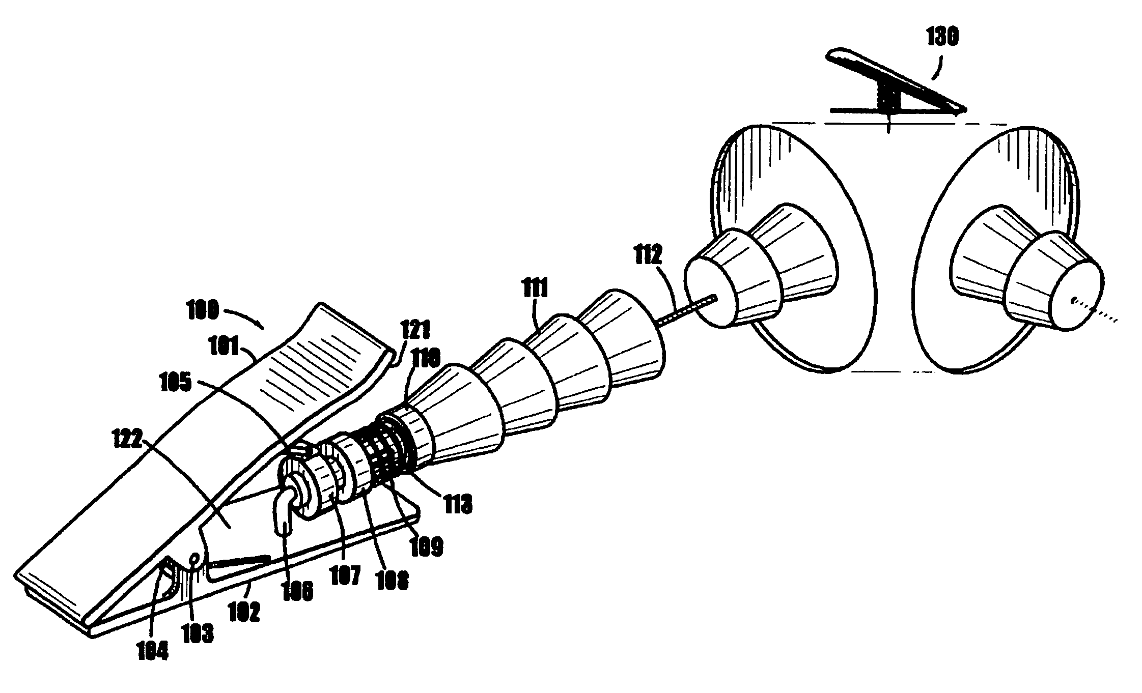
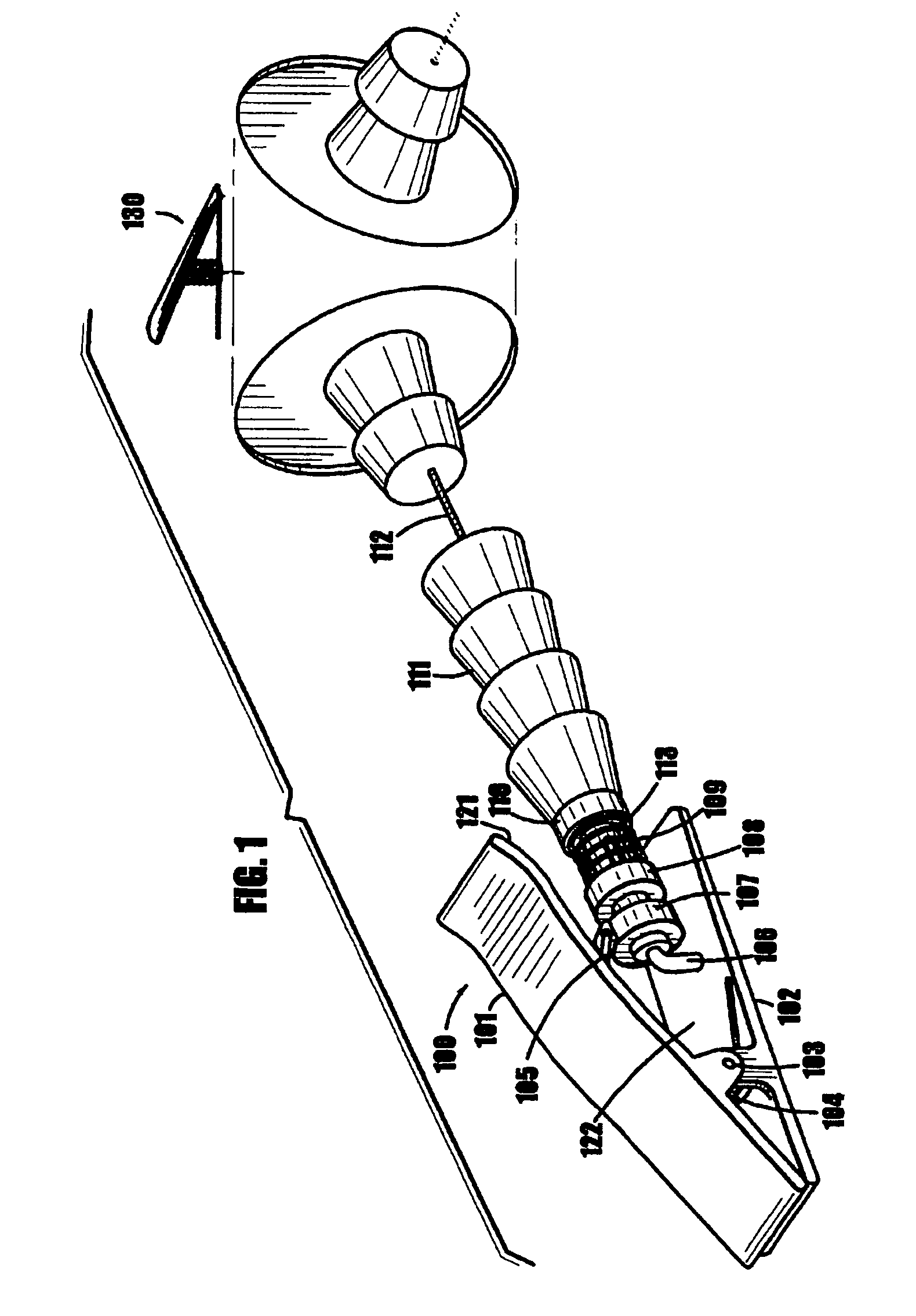
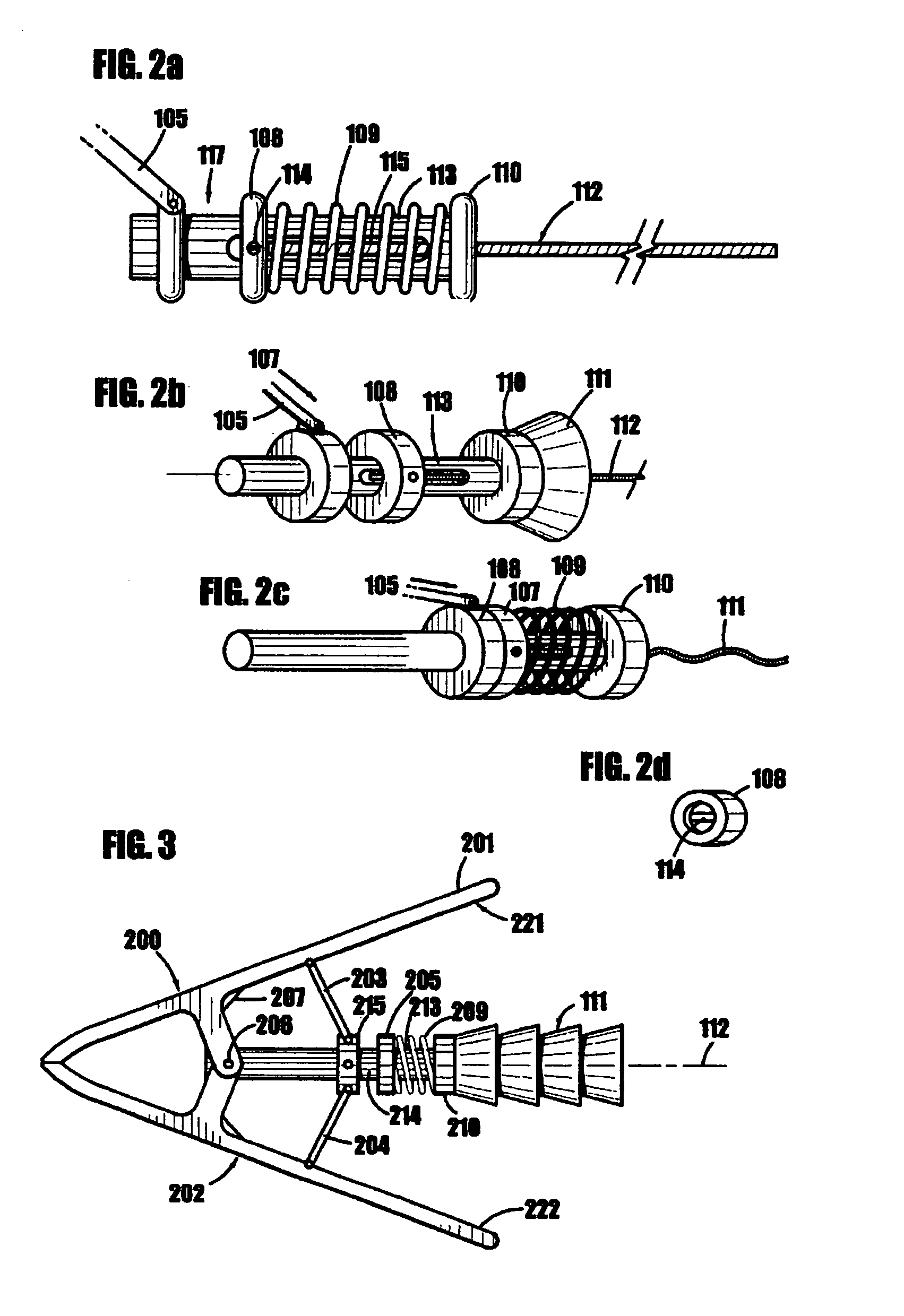
[0051]In one embodiment an apparatus for clamping an object includes a clamp with a first gripping element and a second gripping element that are connected by a pivot rod. The clamp of this embodiment includes a biasing element to maintain the clamp in a closed position in t...


PUM


Abstract

One embodiment of the present invention is directed to a clamping device with an attached arm in which the act of opening the clamp makes the arm flexible and the act of closing the clamp makes the arm rigid. By operating in this manner, the present invention may allow a worker to position the arm (while flexible) in any number of different and easily attainable positions while also allowing the worker to secure a workpiece and immobilize the arm in a single step. In another embodiment of the present invention the arm can be made flexible independently of opening the clamp.

Description

FIELD OF THE INVENTION[0001]One embodiment of the present invention is directed to a clamping device with an attached arm in which the act of opening the clamp makes the arm flexible and the act of closing the clamp makes the arm rigid. By operating in this manner, the present invention may allow a worker to position the arm (while flexible) in any number of different and easily attainable positions while also allowing the worker to secure a workpiece and immobilize the arm in a single step.[0002]In another embodiment of the present invention the arm can be made flexible independently of opening the clamp.[0003]The uses of such a device are numerous, including (but not limited to) many mechanical work projects such as carpentry, plumbing, auto repair, electronics assembly and surgery.[0004]For the purposes of the present application the term cable is intended to refer to any type of wire, rope, cord, string, band, strap, chain or the like.[0005]Further, for the purposes of the prese...

Claims


Application Information

Patent Timeline
Patent Type & Authority Patents(United States)
IPC IPC(8): B25B1/20
CPCB25B5/006B25B5/06F16M11/40F16M13/022F16M13/02Y10T24/314Y10T24/44752
Inventor LA MENDOLA, CHRISTOPHER LOUISHATCH, PAULBUSCHMANN, KRISTIANLOVELL, KEVIN R.PETERS, JOSEPH R.
Owner LA MENDOLA CHRISTOPHER LOUIS
Why Eureka
Try Eureka