Strain relief unit for fiber shuffling device

a strain relief unit and shuffling device technology, applied in the direction of fibre mechanical structure, bundled fibre light guide, instruments, etc., can solve the problems of bending stiffness, impaired optical performance, more prone to damage, etc., and achieve the effect of preventing signal propagation loss

Inactive Publication Date: 2006-01-10
TE CONNECTIVITY CORP
View PDF7 Cites 77 Cited by
  • Summary
  • Abstract
  • Description
  • Claims
  • Application Information

AI Technical Summary

Benefits of technology

[0011]The strain relief unit may also include internal channels extending from the fiber shuffling device to an opening for receiving the jacketed fiber. In this manner, the strain relief unit manages the optical fiber bend radiuses to prevent signal propagation losses.

Problems solved by technology

Applicant has recognized, however, a problem with jacketed ribbons exiting fiber shuffling devices such as the Schott Optical Shuffle™ device.
This is problematic since the optical fibers of the ribbons are not designed to bear significant tensile loads and are therefore more prone to damage and impaired optical performance.
Furthermore, Applicant has recognized the presence of the jacket significantly increases the bending stiffness of the ribbon, and, when bending loads are imposed on the jacketed ribbons, most of the bending occurs over the un-jacketed, bare portion of the ribbon.

Method used


Image

  • Strain relief unit for fiber shuffling device
  • Strain relief unit for fiber shuffling device
  • Strain relief unit for fiber shuffling device

Examples


Embodiment Construction

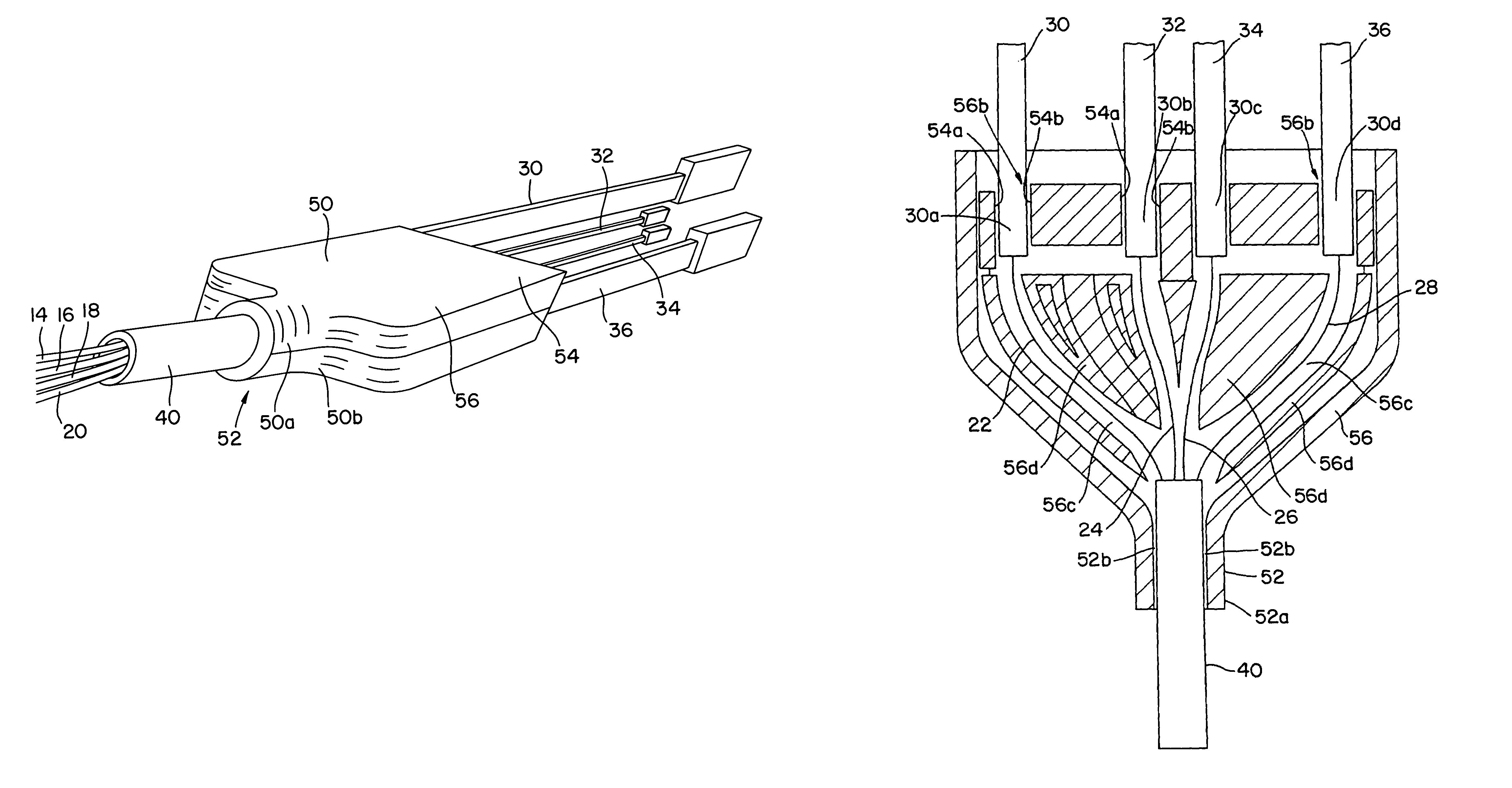
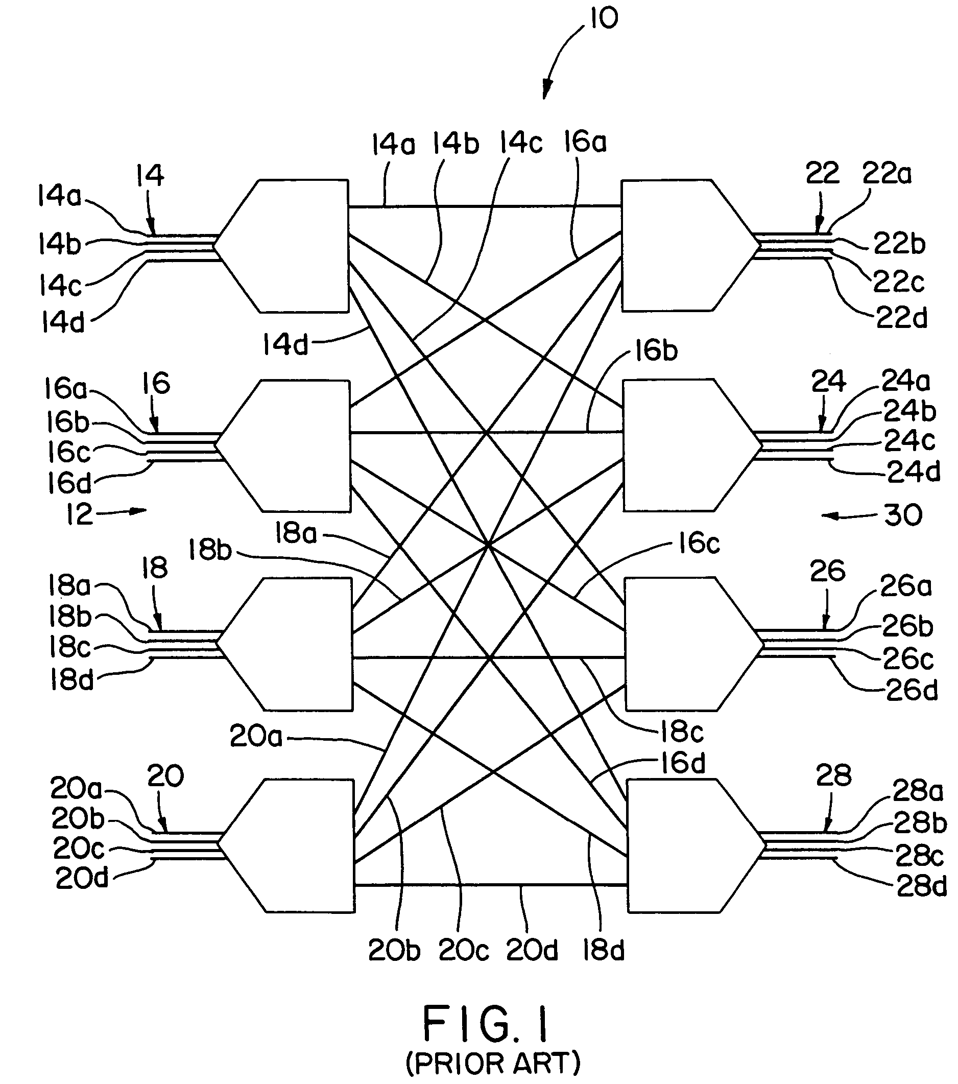
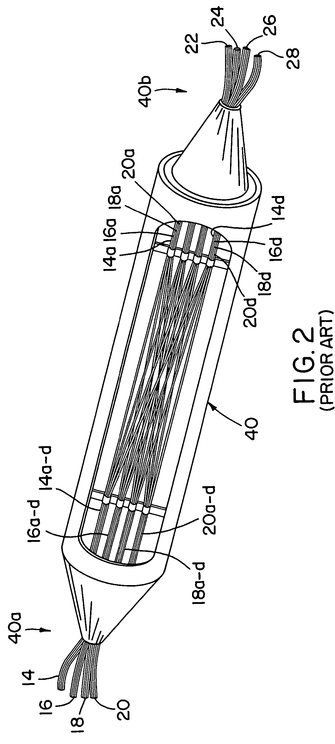
[0016]FIG. 3 is a perspective view of an exemplary strain relief unit 50 in accordance with the present invention for connecting a jacketed bundle or ribbon of optical fibers to a fiber shuffling device 40. For illustrative purposes, the exemplary strain relief unit 50 of FIG. 3 is configured for use with the Schott Optical Shuffle™ device 40 of FIG. 2, although it should be understood that it can be used with any fiber shuffling device. The example of FIG. 3 is consistent with the example of FIG. 1 in that there are four bundles of input signal fibers 14, 16, 18, 20, and that each of these bundles is an unjacketed, ribbonized bundle of four optical fibers. However, it will be understood that the present invention is equally applicable to any number of input signal fibers and fiber bundles, whether ribbonized or unribbonized, and whether jacketed or unjacketed.

[0017]In the example of FIGS. 3 and 4, the individual input signal optical fibers 14a–20d are rearranged (“shuffled”) accord...


PUM


Abstract

A strain relief unit for a fiber shuffling device including a first attachment member adapted for attaching to the fiber shuffling device and a second attachment member connected to said first attachment member and adapted for attaching to a portion of a jacket of an optical fiber. The first and second attachment members may be connected by a support member. The strain relief unit directly connects a jacket of the optical fiber to the fiber shuffling device to relieve the jacketed fiber / ribbon of any load imposed thereon. The strain relief unit defines internal channels from the fiber shuffling device to an opening for receiving the jacketed fiber to limit the optical fiber / ribbon bend radiuses to acceptable levels.

Description

FIELD OF THE INVENTION[0001]The present invention relates to a device for providing strain relief to optical fibers routed through a fiber shuffling device.DISCUSSION OF RELATED ART[0002]Bundles of four, eight or twelve optical fibers are often fused or otherwise bound together in a ribbon. Multi-fiber connectors, such as MT-type connectors, are used to effect a connection between two bundles of fibers or between a bundle of fibers and a device. In the construction of optical fiber circuits using multiple ribbons, it is often necessary to reorganize the fibers such that a fiber bundled as part of one ribbon in one part of the circuit becomes bundled as part of another ribbon in another part of the circuit.[0003]FIG. 1 shows an example of a portion of such an optical fiber circuit 10 having four input signal ribbons 14, 16, 18 and 20 each having four optical fibers 14a–14d, 16a–16d, 18a–18d and 20a–20d, respectively. The circuit portion 10 also has four output signal ribbons 22, 24, ...

Claims


Application Information

Patent Timeline
Patent Type & Authority Patents(United States)
IPC IPC(8): G02B6/44G02B6/04G02B6/38
CPCG02B6/4472G02B6/04G02B6/3887G02B6/4478
Inventor BAECHTLE, DAVID ROBERT
Owner TE CONNECTIVITY CORP
Why Eureka
Try Eureka