
Transient control technology circuit

a technology of transient control and circuit, applied in emergency protective arrangements for limiting excess voltage/current, electrical devices, and arrangements responsive to excess voltage, etc., can solve problems such as affecting electronic devices, changing the operating frequency range of connected equipment, and severely damage or destroy electronic devices

Inactive Publication Date: 2013-08-15
TRANSTECTOR SYST INC
View PDF9 Cites 5 Cited by
  • Summary
  • Abstract
  • Description
  • Claims
  • Application Information

AI Technical Summary

Benefits of technology

This patent describes an apparatus and method for protecting electronic devices from surges. The device contains a housing with a cavity, an input port, and an output port. A first transistor is positioned within the housing with three terminals that automatically switch between conducting and non-conducting configurations. The conducting configuration allows signal propagation and the non-conducting configuration prevents it. The device also contains at least one resistor and at least one diode. The resistor connects to the third terminal of the first transistor to bias it, while the diode diverts a surge signal from the input port to the ground. Additionally, there is a second transistor that controls the switching of the first transistor from the conducting to non-conducting configuration. The technical effect of this invention is that it provides a fast and effective way to protect electronic devices from surges, ensuring their safe operation.

Problems solved by technology

Surge variations in power and transmission line voltages, as well as noise, can change the operating frequency range of connected equipment and severely damage or destroy electronic devices.
Electronic devices impacted by these surge conditions can be very expensive to repair or replace.
The effects of power surges from overvoltages or overcurrents upon commercial or military aircraft systems can cause dangerous disruptions of the various systems aboard the aircraft and must be mitigated for safe airline travel.
However, conventional protection circuits typically employ fuses that are configured to open during an overcurrent fault condition.
Once these fuses or protection elements have opened or otherwise tripped to prevent propagation of a surge, the connected electrical system exists in a protected state, but the circuit can cause faults in a connected system of the aircraft.
Indeed, due to the interoperability of many systems with each other for proper aircraft functionality or operation, the propagation of a fault from a first system to a second system due to a surge protection scheme may be extremely undesirable and damaging to safe operation of the aircraft.

Method used


Image

  • Transient control technology circuit
  • Transient control technology circuit
  • Transient control technology circuit

Examples


Embodiment Construction

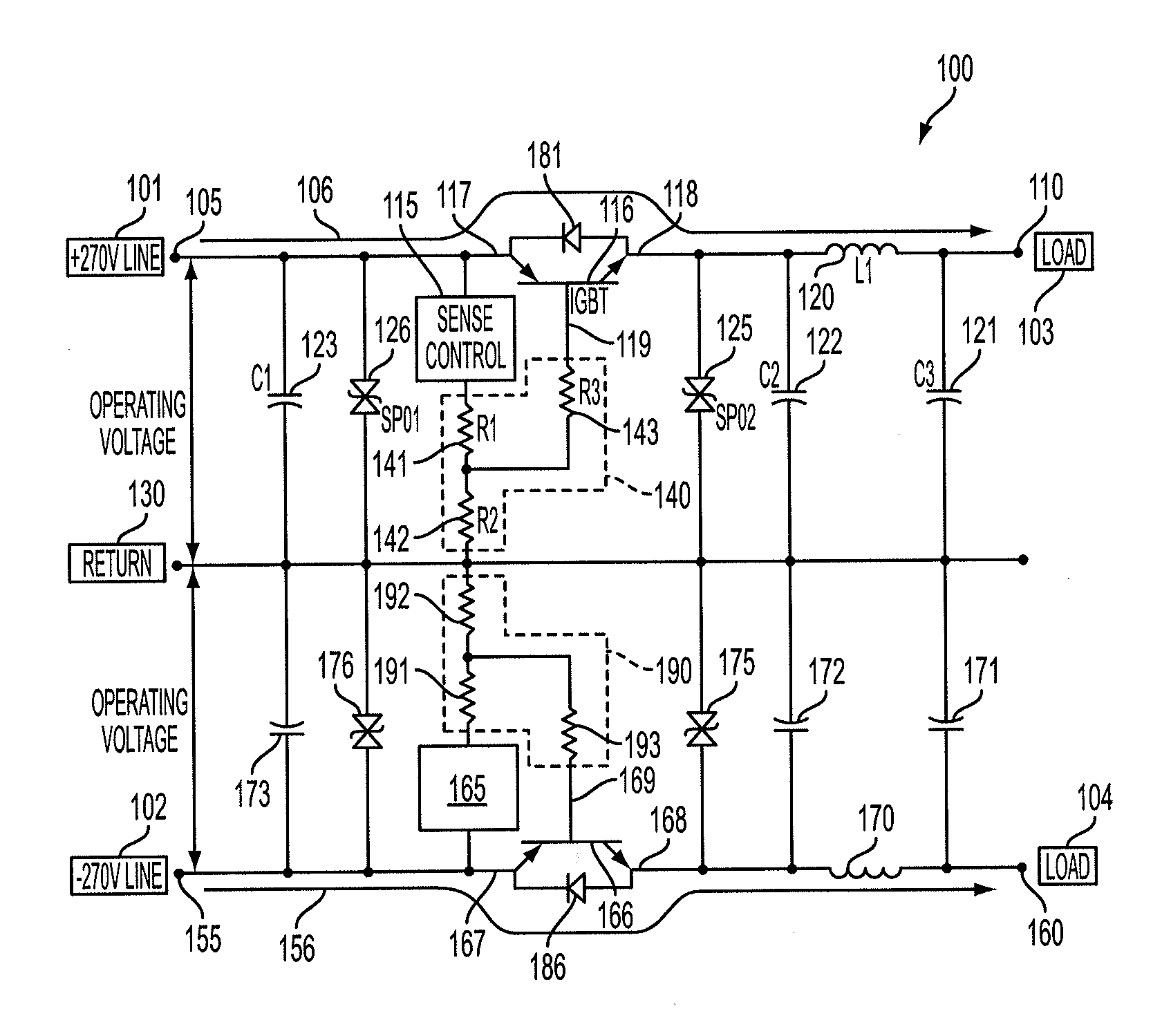
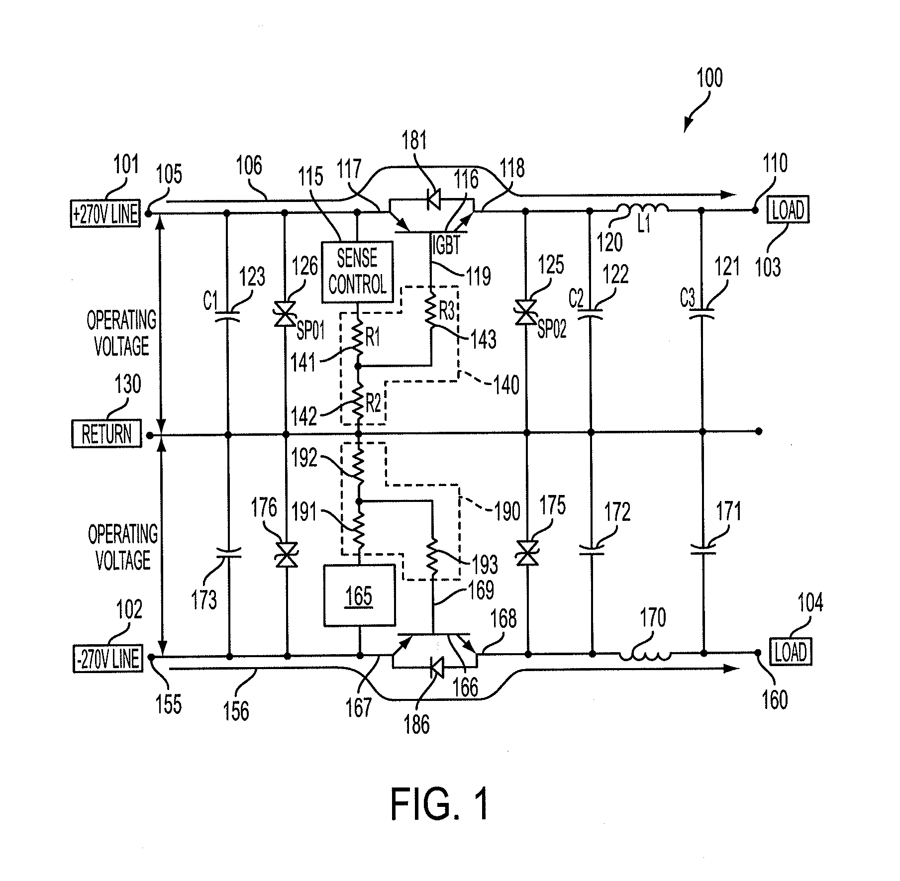
[0014]Referring to FIG. 1, a schematic circuit diagram of a transient control technology surge protection circuit 100 is shown. The surge protection circuit 100 operates to protect any connected loads (103, 104) from an electrical surge that could otherwise damage or destroy the loads (103, 104). The protected loads (103, 104) can be any form of electric equipment, for example electrical units aboard an aircraft, communications equipment, cell towers, base stations, PC computers, servers, network components or equipment, network connectors or any other type of surge sensitive electronic equipment. The surge protection circuit 100 includes a number of different electrical components, such as capacitors, resistors, inductors, diodes and IGBTs. For illustrative purposes, the surge protection circuit 100 will be described with reference to specific capacitor, resistor, inductor, diode or IGBT values and configurations to achieve specific surge protection or energy storage capabilities. ...


PUM


Abstract

An active surge suppression or protection circuit for protecting hardware or equipment from electrical surges. During operation when no surge condition is present, the circuit passes signals from an input source to a connected load along a signal path. When a surge is present, the circuit automatically senses and diverts the surge away from the signal path. A switching component is provided along the signal path for either allowing transmission or preventing transmission of a signal along the signal path. Upon diverting the surge, the circuit automatically changes the switching component from a closed state (for allowing transmission) to an open state (for preventing transmission). After the surge has passed, the circuit automatically changes the switching component from the open state to the closed state. Other automatic circuit behaviors may also be achieved in response to the diversion of a surge condition from the signal path.

Description

CROSS REFERENCE TO RELATED APPLICATIONS[0001]This application claims the benefit and priority of U.S. Provisional Application No. 61 / 597,631 entitled Transient Control Technology Circuit, filed on Feb. 10, 2012, the entire contents of which are hereby incorporated by reference herein.BACKGROUND[0002]1. Field[0003]The present disclosure relates generally to surge protection circuits and improvements thereof. More particularly, the present disclosure relates to automatically resettable surge protection circuits and improvements thereof.[0004]2. Description of the Related Art[0005]Communications equipment, computers, home stereo amplifiers, televisions and other electronic devices are increasingly manufactured using a variety of electronic components that are vulnerable to damage from electrical energy surges. Surge variations in power and transmission line voltages, as well as noise, can change the operating frequency range of connected equipment and severely damage or destroy electro...

Claims


Application Information

Patent Timeline
Patent Type & Authority Applications(United States)
IPC IPC(8): H02H3/02
CPCH02H3/021H02H9/042H02H3/22
Inventor HENDRICKS, MARK L.NGUYEN, ERIC
Owner TRANSTECTOR SYST INC
Learn More