Efficient and optimal channel encoding and channel decoding in a multiple access communications system

a communication system and multiple access technology, applied in the field of multiple access communication systems, can solve the problems of increasing complexity exponentially with the number of users, affecting or diminishing one criterion generally, and requiring a large amount of decoding procedures

a communication system and multiple access technology, applied in the field of multiple access communication systems, can solve the problems of increasing complexity exponentially with the number of users, affecting or diminishing one criterion generally, and requiring a large amount of decoding procedures

US6985699B2Active Publication Date: 2006-01-10COLLISION COMM INC

Image

  • Efficient and optimal channel encoding and channel decoding in a multiple access communications system
  • Efficient and optimal channel encoding and channel decoding in a multiple access communications system
  • Efficient and optimal channel encoding and channel decoding in a multiple access communications system

Examples


Embodiment Construction

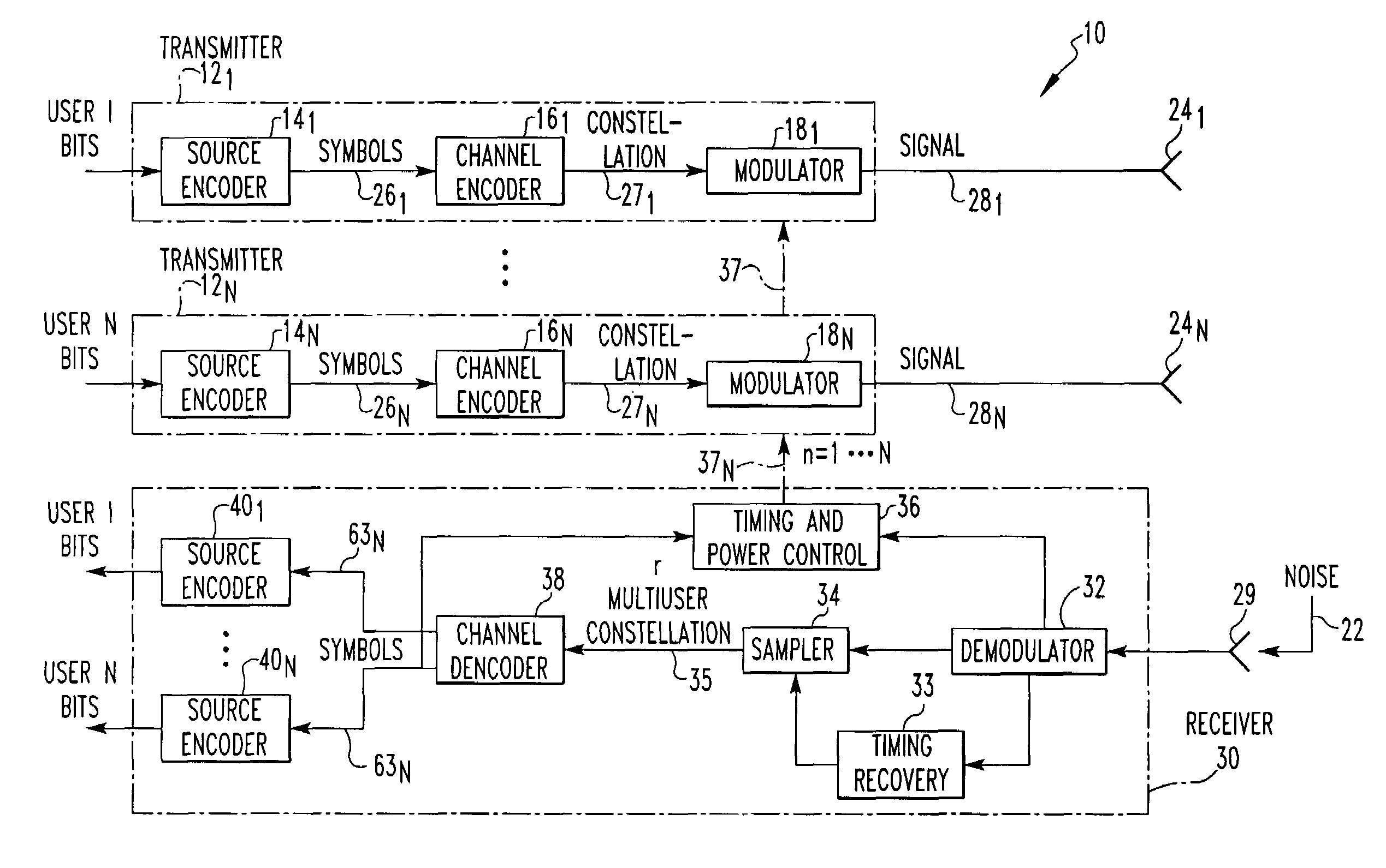
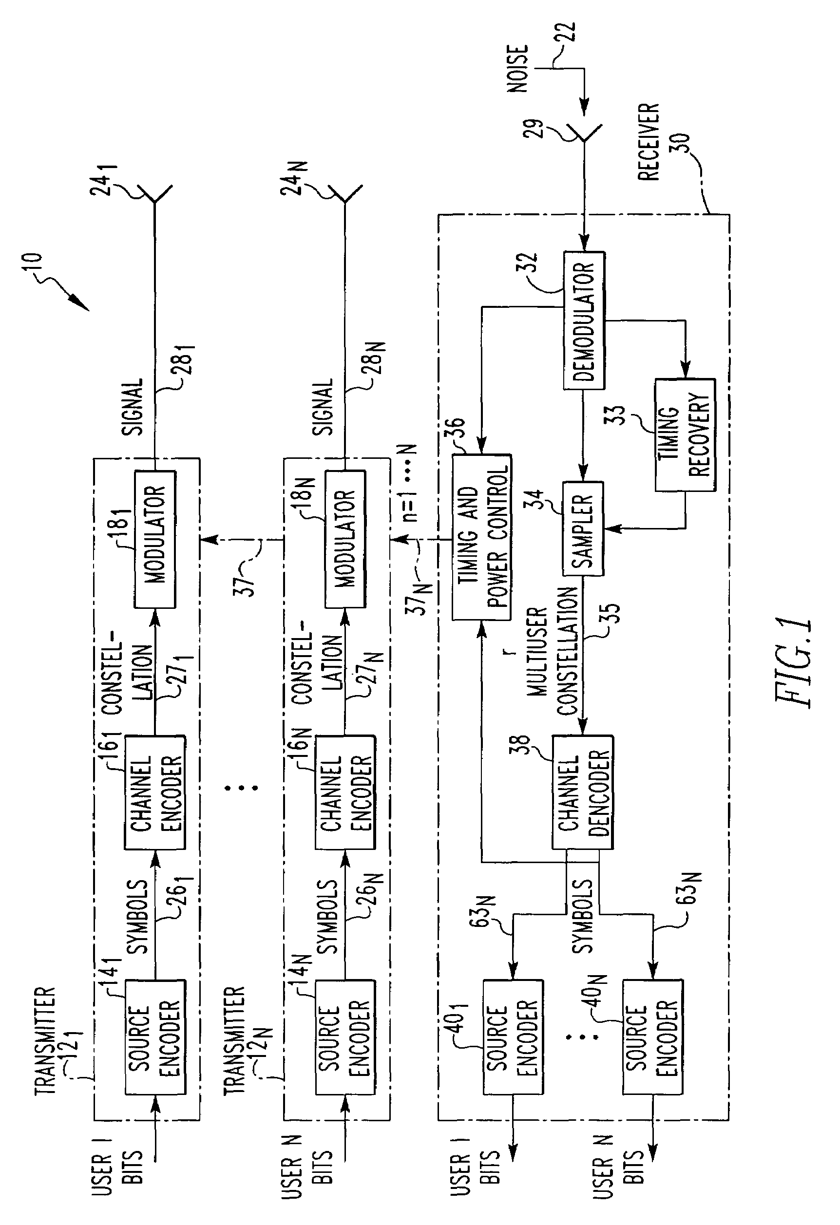
[0036]Referring to FIG. 1, a block diagram is shown of a typical multiuser access communication system 10. An information source generates a sequence of bits at some rate, and the multiple transmitters 121–12N and single receiver 30 combination has to allow the information to be sent reliably across free space via antennas 241–24N or via a hard wired connection. The preferred embodiment is a wireless implementation, wherein the signal output 281–28N is transmitted by a plurality of corresponding antennas 241–24N that is transmitted into free space and combined and picked up by the receiver antenna 29. However, it is readily apparent to those skilled in the art that the output of the signals 281–28N can be a wired connection without employing antennas or wireless interference, thus reducing noise 22. Note, that as defined herein, the term β€˜users’ refers to any multiple source of information bits.

[0037]There are multiple transmitters 121–12N, each corresponding to a user of the system...


PUM


Abstract

A method of channel encoding and channel decoding in a multiple access communication system wherein the channel decoding requirements increase linearly and not exponentially as the number of users increase. A channel encoder converts alphabetic symbols into a preselected geometric representation of a hexagonal lattice known as a symbol constellation. A channel decoder converts the received symbol constellation into a replication of the alphabetic symbols. Each user has a specially defined symbol set that allows the linear-complexity decoding operation.

Description

BACKGROUND OF THE INVENTION[0001]1. Field of the Invention[0002]This invention relates generally to a multiple access communication (MAC) system, and in particular, to an apparatus and method of channel encoding and channel decoding using a multiuser symbol constellation confined to a hexagonal lattice with each user having a defined symbol set.[0003]2. Description of Related Art[0004]A multiple access communication (MAC) system is a communication system in which a large number of users share a common communication channel to transmit information to a common receiver. Examples of this are the uplink path in a mobile-to-cellular phone tower or in a ground-to-satellite communication system. While the goals of MAC system designs can vary, they are generally concerned with efficient use of channel bandwidth, ease of decoding multiple user transmissions, providing a mechanism for users to enter the system, and reallocating resources when users leave the system. These goals are often at o...

Claims


Application Information

Patent Timeline
10 Jan 2006
Publication
US6985699B2
IPC
H04B15/00; H04Q7/20; H04L5/02; H04L5/12; H04L27/34; H04L27/38
CPC
H04L5/02; H04L27/3405; H04L27/38; H04L5/12
Inventors
FIORE, PAUL D.