

Pole structure to relieve adjacent track writing
a pole structure and adjacent track technology, applied in the field of magnetic recording systems, can solve the problems of inadvertently deleting adjacent tracks, difficult control of track width, and using the conventional notch b>16/b>,
- Summary
- Abstract
- Description
- Claims
- Application Information
AI Technical Summary
Benefits of technology
Problems solved by technology
Method used
Image

Examples
second embodiment
[0040]As discussed above with respect to FIGS. 4A and 4B, in the PDZT head 100′ shown in FIGS. 5A and 5B the magnetic field at the back of the pedestal 104′, in the second portion of the gap 108′, is reduced. As a result, the notch 106′ is less likely to be saturated. Consequently, the PDZT head 100′ is less likely to erase adjacent tracks. Furthermore, because the notch 106′ is formed using the P2110 shadow mask, the PDZT head 100 still has improved writeability and control of the track width.
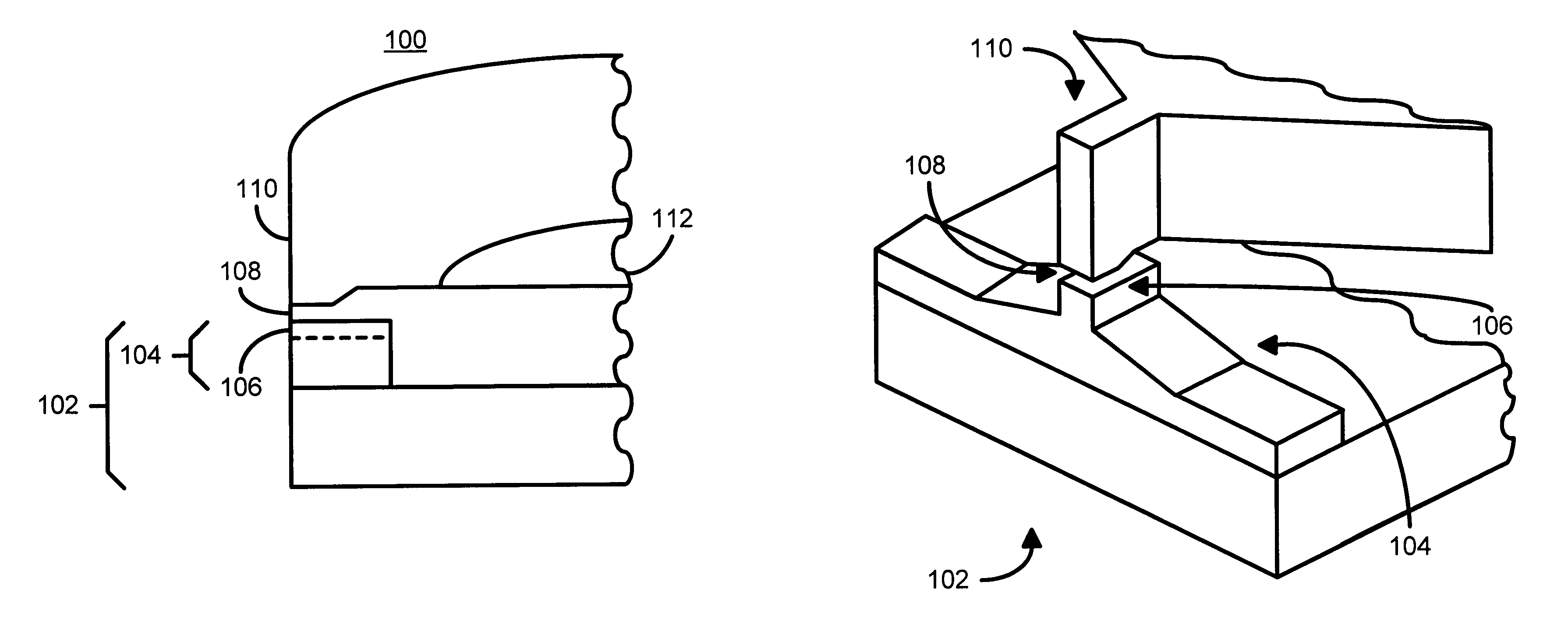
[0041]FIGS. 6A and 6B, respectively, depict perspective and side views, respectively of a portion of a third embodiment of a PDZT head 100″ in accordance with the present invention. Many of the components of the PDZT head 100″ are analogous to the PDZT head 100. Consequently, portions of the PDZT head 100″ are labeled similarly. For example, the PDZT head 100 includes a gap 108, while the PDZT head 100″ includes a gap 108″. The gap 108″ has a first portion near the front of the PDZT head 100″ ...
third embodiment
[0044]For the same reasons as discussed with respect to FIGS. 4A and 4B, in the PDZT head 100′″ shown in FIGS. 7A and 7B the magnetic field at the back of the pedestal 104′″, in the second portion of the gap 108′″, is reduced. Because the gap 108′″ is thicker at the back than at the front of the pedestal 104′″ in the PDZT head 100′″ shown in FIGS. 7A and 7B the magnetic field at the back of the pedestal 104′″, in the second portion of the gap 108′″, is reduced. Moreover, the notch 106′″ is not completely milled through the pedestal 104′″. As a result, the notch 106′″ is thinner at the back of the pedestal 104′″ than at the front. As a result, there is even more area for magnetic flux from the P2106′″ to P1102′″ to spread. The magnetic field at the back of the notch 106′″ is further reduced. As a result, the notch 106′″ is less likely to be saturated. Consequently, the PDZT head 100′″ is less likely to erase adjacent tracks. Moreover, because the notch 106′″ is formed using the P2110...
fifth embodiment
[0047]FIG. 9 is a high level flow-chart of one embodiment of a method 200 for providing a PDZT head 100, 100′, 100″, 100′″ or 100″″ in accordance with the present invention. The first pole, P1, with a pedestal is provided, via step 202. Step 202 includes depositing the bottom portion of the pole, depositing the pedestal and adjacent insulator and performing a chemical mechanical polish (CMP) to planarize the PDZT head and set the height of the pedestal. A gap in accordance with the present invention is then provided, via step 204. The gap provided in step 204 has two portions. The first portion of the gap is near the front of the pedestal at the air bearing surface, while the second portion of the gap is near the back of the pedestal. Step 204 also includes ensuring that the second portion of the gap is thicker than the first portion of the gap. In a preferred embodiment, the second portion of the gap is approximately seven hundred Angstroms thicker than the first portion of the gap...
PUM
 Abstract
Description
Claims
Application Information