Exercise bar cord impingement assembly

a technology of impingement assembly and exercise bar, which is applied in gymnastic exercise, resilient force resistors, weights, etc., can solve the problems of unattractive and cumbersome alteration, affecting the effect of lengthening cord (b>20/b>), and requiring a large amount of material to achieve the effect of shortening cord

Inactive Publication Date: 2006-01-24
TERRY DOUGLAS C +1
View PDF15 Cites 22 Cited by
  • Summary
  • Abstract
  • Description
  • Claims
  • Application Information

AI Technical Summary

Benefits of technology

[0037]The handgrip connection block's neck (123, 133% the portion of the handgrip (120, 130) which is emplaced within the tunnel's second opening (17)—may take any one of several conceivable forms in cross-section. Rotational positioning of the connection blocks (121, 131)—say, to dispose a handgrip emplacement slot (126, 136) and the body's emplacement slot (14) or channel (11) in deliberate misalignment—is made feasible by configuring the block's necks (123, 133) with axial symmetry. Obstructions otherwise encountered during rotational positioning upon a prior art exercise bar (100), such as the older-fashioned enwrapment pegs, are eliminated by streamlining the bar body (10) to confer upon it (10) what is designated herein to be continuously contoured projection.

Problems solved by technology

The undertaking of the wrapping convenience to effectually shorten cord (20) length came only at a cost, however.
That, however, resulted in a rather bulky arrangement and the handgrip (120) rotational difficulties presented by cord (20) enwrapment pegs discussed supra had to be reckoned with.
Unfortunately, however, as with the solid handgrip (120), that device can be oriented in but one direction upon emplacement.
It may not be feasible to work with an impinger (200) either kept separately from the combination—in which case it (200) would be vulnerable to misplacement or loss—or installed on the body of a retrofitted exercise bar (100), an alteration which would likely prove unattractive and cumbersome.
Mere substitution of the latter (21, 22) for the former (121, 131) would result in an unwanted very loose fit, possibly even allowing the stoppered cord (20, 22) to slip out of place altogether during use.

Method used


Image

  • Exercise bar cord impingement assembly
  • Exercise bar cord impingement assembly
  • Exercise bar cord impingement assembly

Examples


Embodiment Construction

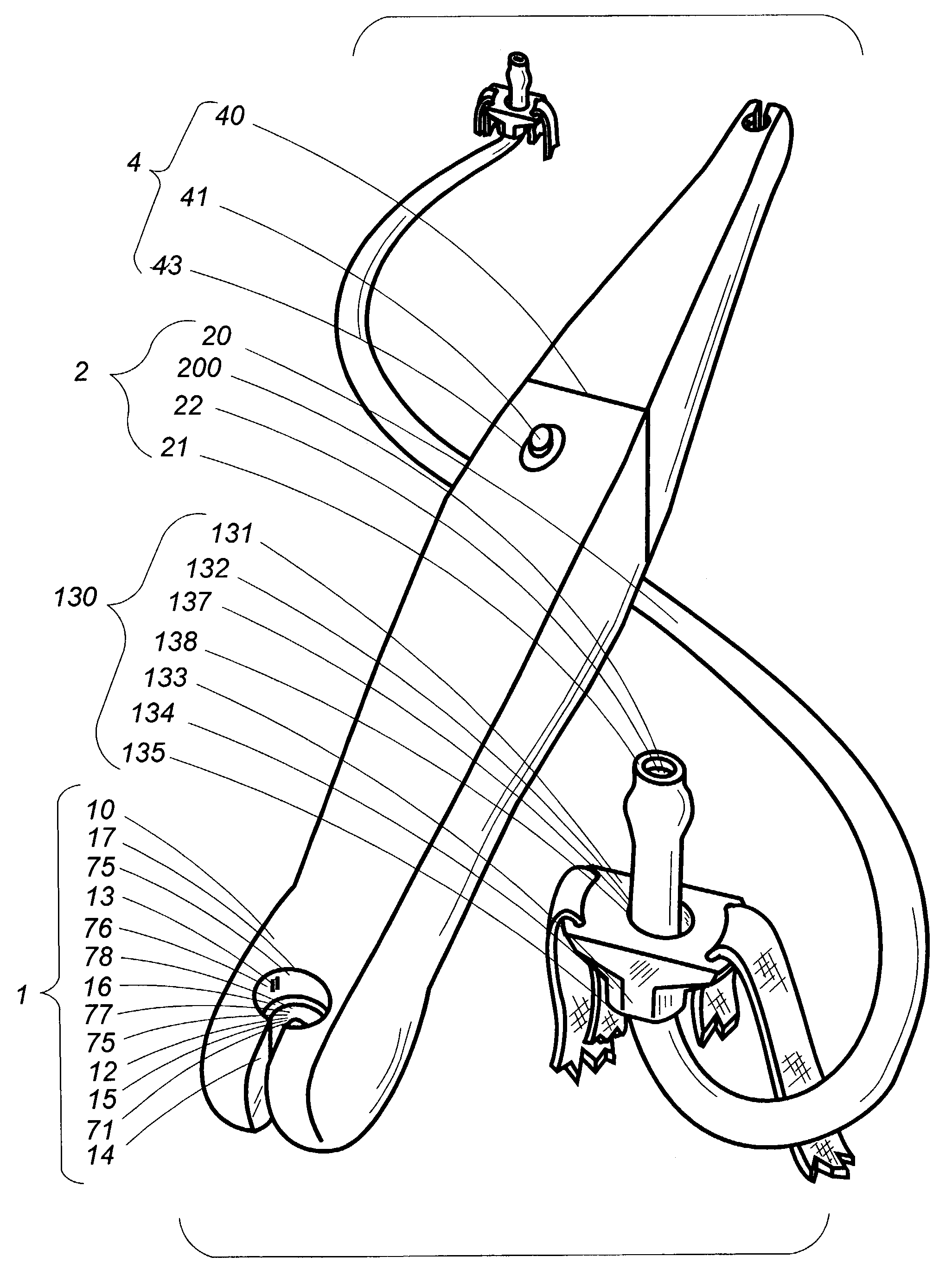
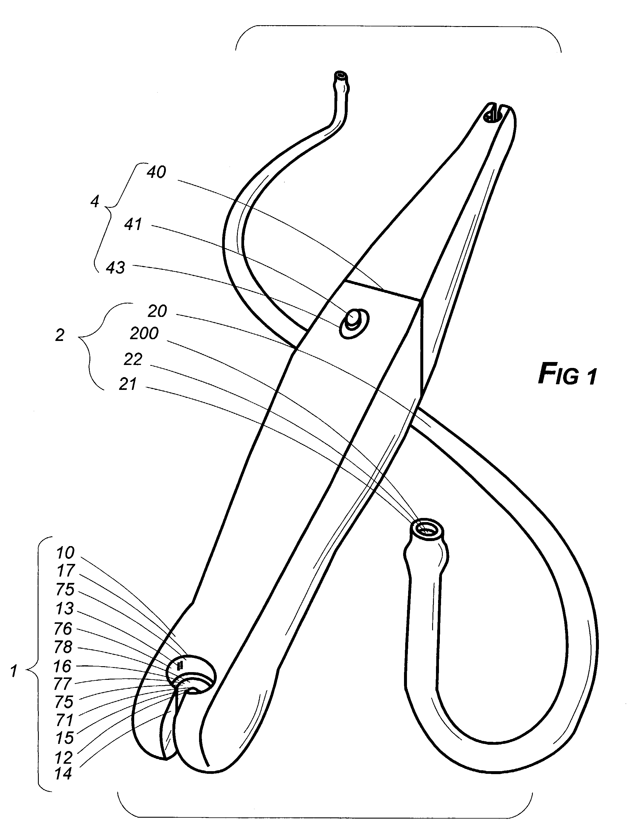
[0059]The subject of this application is a lifting bar and stretchable cord assembly comprised of an exercise bar assembly (1) and an elastic exercise cord assembly (2).

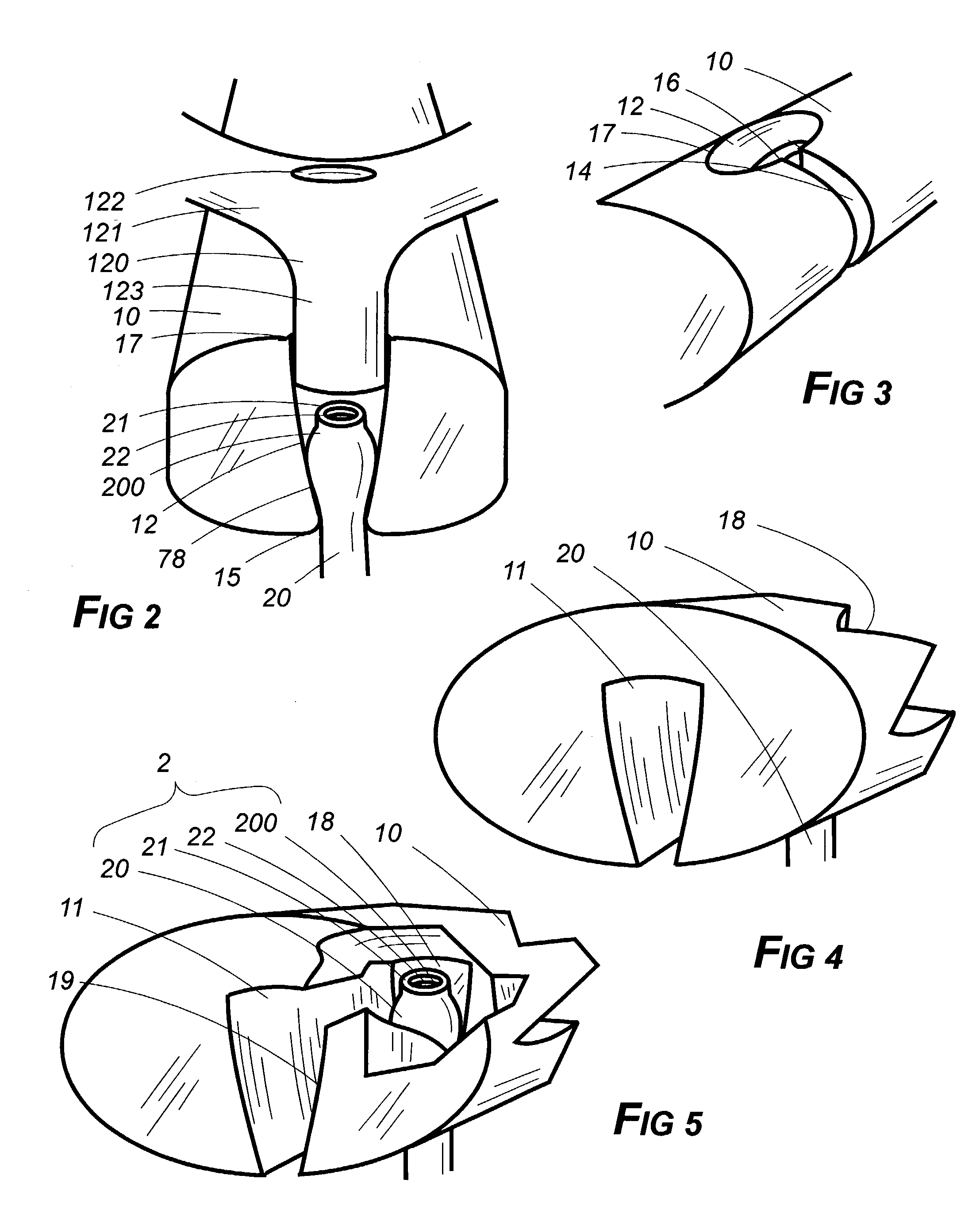
[0060]In simplest embodiment, the first of the two general components—the exercise bar assembly (1)—comprises an elongated body (10), an opposing pair of transversely disposed cord tunnels (12) therein (10). An alternative embodiment substituting underlying cord emplacement nests (18) for the tunnels (12) is also provided herein.

[0061]By transversely disposed is meant that each tunnel (12) is oriented to cross through the interior of the bar's body (10) from one longitudinal side to an opposing longitudinal side thereof (10)—such as from some point along the length of the top to the bottom of a horizontally disposed body (10). By definition, of course, any tunnel has two oppositely disposed ends or openings and that (12) which comprises part of this embodiment of the subject hereof is no exception. One of the ends of...


PUM


Abstract

An exercise bar cord impingement assembly permits exercise in two modes, defined in terms of how cord anchoring is arranged. There is a tunnel or, alternatively, a nest at each end of the bar where snug connection—a direct one—with a conventionally stoppered cord end is made. Handgrips may be employed with the assembly instead, in which case, each cord end is impinged not within the bar's body but within the grips—an indirect connection. A tunnel may have shared emplacement wells within it, preferably situated concentrically, one for the impinged cord, the other for an emplaced handgrip connection block. A handgrip's connecting block may be shaped in any of several ways for rotational positioning advantages. Cord emplacement slots are preferably present in both the bar and the block. In models having nests instead of tunnels, a cord emplacement channel is necessarily provided to get the impinged cord seated into place.

Description

[0001]This instrument, filed under 37 CFR 1.53(b) and 1.78, invoking the provisions of 35 U.S.C. 120, is a Continuation-in-Part of presently copending application Ser. No. 10 / 184,239 entitled “Exercise Bar and Cord Assembly”, filed Jun. 26, 2002.BACKGROUND OF THE INVENTION[0002]1. Field of the Invention[0003]Exercise equipment[0004]2. Description of the Prior Art[0005]Occasionally a descriptive term in this application may be shortened so as to recite only a part rather than the entirety thereof as a matter of convenience and to avoid needless redundancy. In instances in which that is done, applicant intends that the same meaning be afforded each manner of expression. Thus, the term exercise bar's block impingement nodes (13) might be used in one instance but in another, if meaning is otherwise clear from context, expression might be shortened to impingement nodes (13) or merely nodes (13). Any of those forms is intended to convey the same meaning.[0006]The term attach or fasten or ...

Claims


Application Information

Patent Timeline
Patent Type & Authority Patents(United States)
IPC IPC(8): A63B21/00A63B21/02A63B21/055A63B21/072A63B21/16
CPCA63B21/0552A63B21/00069A63B21/0414Y10S482/907A63B21/0557A63B21/0724A63B21/16A63B21/0555
Inventor NAULT, JAMES EDWARDHINDS, ROBERT SYLVESTER
Owner TERRY DOUGLAS C
Why Eureka
Try Eureka