Reinforced cord well lifting bar assembly

a well-reinforced cord technology, applied in the field of exercise equipment, can solve the problems of difficulty in achieving the effect of shortening the cord (b>20/b>) length, and the difficulty of achieving the effect of shortening the cord (b>20/b>) length, and achieve the effect of reducing the difficulty of achieving the effect of shortening the cord (b>20/b>) length, and avoiding the possibility of second

Inactive Publication Date: 2008-09-04
TERRY DOUGLAS C
View PDF17 Cites 8 Cited by
  • Summary
  • Abstract
  • Description
  • Claims
  • Application Information

AI Technical Summary

Benefits of technology

[0040]The handgrip connection block's neck (123, 133)—the portion of the handgrip (120, 130) which is emplaced within the tunnel's second opening (17) —may take anyone of several conceivable forms in cross-section. Rotational positioning of the connection blocks (121, 131}—say, to dispose a handgrip emplacement slot (126, 136) and the body's emplacement slot (14) or channel (11) in deliberate misalignment—is made feasible by configuring the block's necks (123, 133) with axial symmetry. Obstructions otherwise encountered during rotational positioning upon a prior art exercise bar (800), such as the older-fashioned enwrapment pegs, are eliminated by streamlining the bar body (10) to confer upon it (10) what is designated herein to be continuously contoured projection.

Problems solved by technology

The undertaking of the wrapping convenience to effectually shorten cord (20) length came only at a cost, however.
The problem is particularly troublesome as the elongated body is raised and lowered in exercise tending to twist or rotationally curl the bar's (800) body out of the operator's grip, depriving the operator of the ordinarily sought-after benefits expected from operation of an elastically anchored lifting bar (800) in either mode of exercise.
That, however, resulted in a rather bulky arrangement for which no second mode options were possible and the handgrip (120) rotational difficulties presented by cord (20) enwrapment pegs discussed supra had to be reckoned with.
Unfortunately, however, as with the solid handgrip (120), that device can be oriented in but one direction upon emplacement.
It may not be feasible to work with an impinger (200) either kept separately from the assembly—in which case it (200) would be vulnerable to misplacement or loss—or installed on the body of a retrofitted exercise bar (800) an alteration which would likely prove unattractive and cumbersome.
Mere substitution of the latter (21, 22) for the former (121, 131) would result in an unwanted very loose fit, possibly even allowing the stoppered cord (20, 22) to slip out of place altogether during use.
Too shallow a wall confers some degree of instability upon the system, permitting a stressful rocking, like effect upon the connection.
It has been observed that the vertical thickness of the bar's body itself (10) does not consistently provide the sought-after retention security.
There is concern, however, that thickening the body (10) would make it (10) cumbersome and impair easy-to-grip configuration.

Method used


Image

  • Reinforced cord well lifting bar assembly
  • Reinforced cord well lifting bar assembly
  • Reinforced cord well lifting bar assembly

Examples


Embodiment Construction

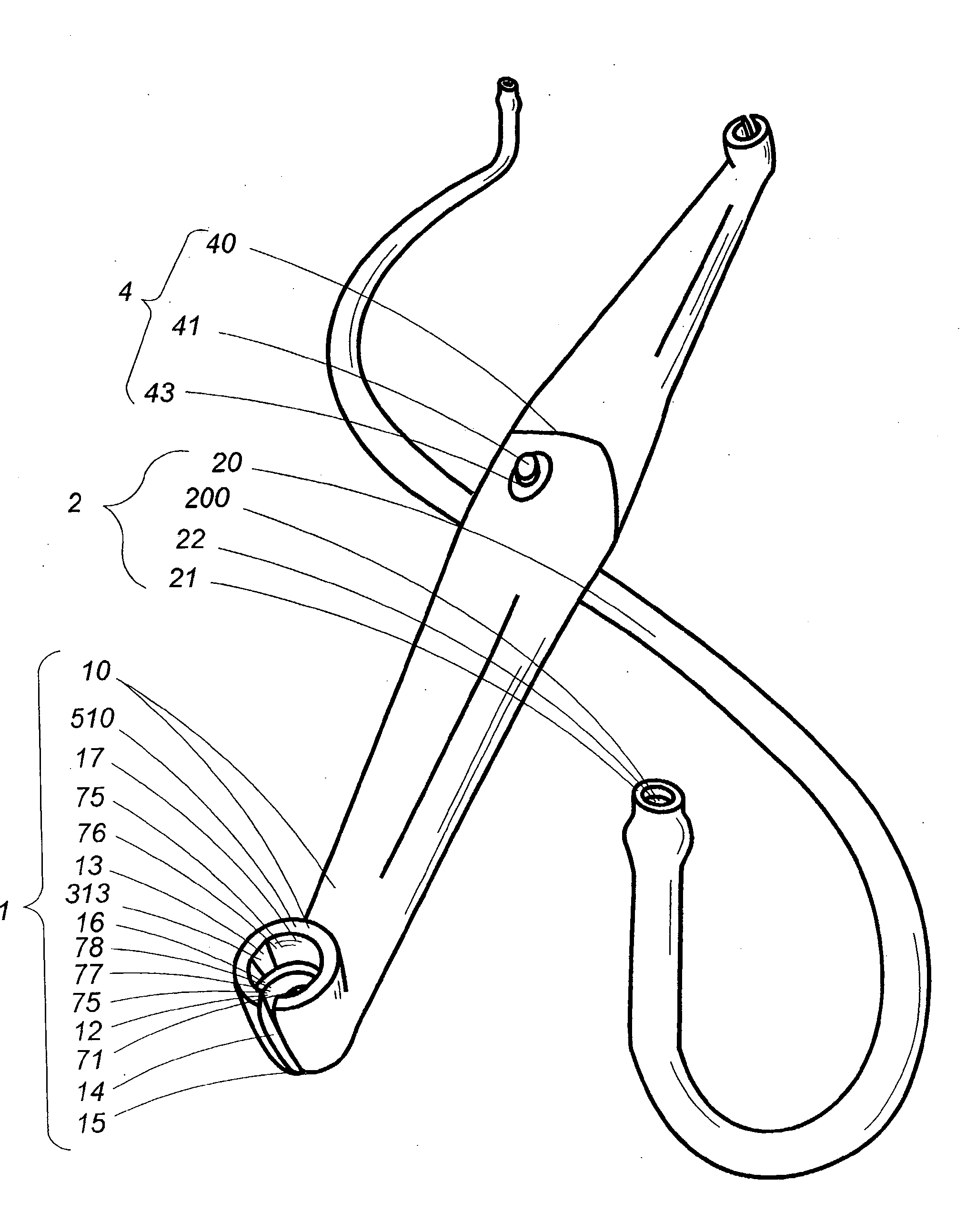
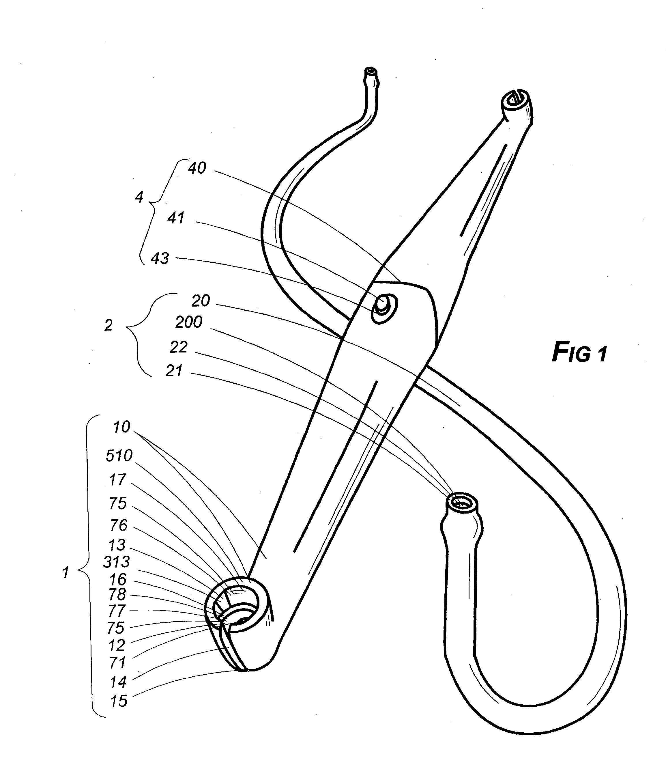
[0064]The subject of this application is a reinforced cord well’ lifting bar assembly comprised of an exercise bar assembly (1) and an elastic exercise cord assembly (2).

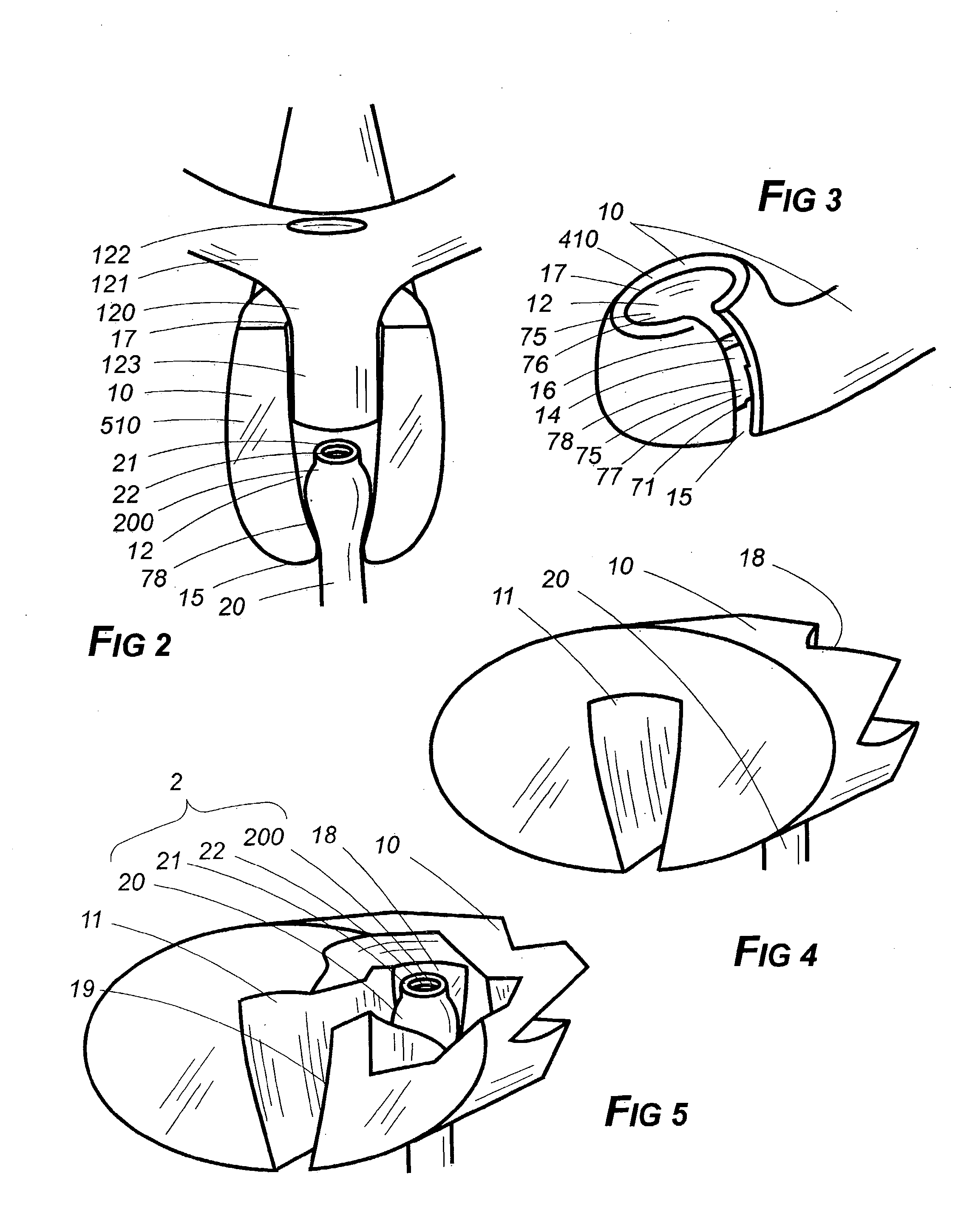
[0065]In simplest embodiment, the first of the two general components—the exercise bar assembly (1) —comprises an elongated body (10), an opposing pair of transversely disposed cord tunnels (12) therein (10). An alternative embodiment substituting underlying cord emplacement nests (18) for the tunnels (12) is also provided herein.

[0066]By transversely disposed is meant that each tunnel (12) is oriented to cross through the interior of the bar's body (10) along an axis, part of which extends from one longitudinal side to an opposing longitudinal side thereof (10) —such as from some point along the length of the top to the bottom of a horizontally disposed body (10). By definition, of course, any tunnel has two oppositely disposed ends or openings and that (12) which comprises part of this embodiment of the subject he...


PUM


Abstract

An exercise bar cord impingement assembly permits exercise in two modes, defined in terms of how cord anchoring is arranged. It also permits exercise to be conducted either with a stretchable cord and handgrip together connected to the bar's body or just the stretchable cord itself so connected. In either case, there are slots in the bar's body to slide the cord through. Specially shaped wells or nests accommodate impingement of the elastic cord and firm handgrip emplacement. The ends of the bar's body are preferably shaped into pipe bowl configuration disposed to insure a good fit and avoid torque.

Description

[0001]This application is a continuation of application Ser. No. 10 / 602,928, filed Jun. 23, 2003, entitled REINFORCED CORD WELL LIFTING BAR ASSEMBLY, which is a continuation-in-part of application Ser. No. 10 / 184,239 entitled EXERCISE BAR AND CORD CONNECTOR, filed Jun. 26, 2002, which are incorporated herewith in their entirety.BACKGROUND OF THE INVENTION FIELD OF THE INVENTION[0002]1. The Field of the Invention[0003]The present invention is related to exercise equipment, and more specifically to a reinforced cord well lifting bar assembly.[0004]2. Description of the Prior Art[0005]Occasionally a descriptive term in this application may be shortened so as to recite only a part rather than the entirety thereof as a matter of convenience and to avoid needless redundancy. In instances in which that is done, applicant intends that the same meaning be afforded each manner of expression. Thus, the term exercise bar's block impingement nodes (413) might be used in one instance but in anoth...

Claims


Application Information

Patent Timeline
Patent Type & Authority Applications(United States)
IPC IPC(8): A63B21/00
CPCA63B21/00061A63B21/0414A63B21/0552A63B21/0555A63B2208/0204A63B21/16A63B21/1663A63B2021/169A63B2071/027A63B21/0724A63B21/169
Inventor TERRY, DOUGLAS C.HINDS, ROBERT S.BONNEVILLE, LOYD W.
Owner TERRY DOUGLAS C
Why Eureka
Try Eureka