System for controlling the in situ orientation of a vehicle headlamp, and method of use

a technology for in situ orientation and vehicle headlamps, which is applied in vehicle headlamps, special data processing applications, lighting support devices, etc., can solve the problems of system drawbacks, driver of vehicle no longer having sufficient visibility to take in the situation around him, and dazzle the driver of vehicle coming in the opposite direction

Inactive Publication Date: 2006-01-24
VALEO VISION SA
View PDF12 Cites 58 Cited by
  • Summary
  • Abstract
  • Description
  • Claims
  • Application Information

AI Technical Summary

Problems solved by technology

They may therefore dazzle the drivers of vehicles coming in the opposite direction.
The driver of the vehicle then no longer has sufficient visibility to be able to take in the situation around him.
However, this system has drawbacks.
This is because the sensors are placed close to the wheels, that is to say at points which are difficult for a human or robot to access during manufacture of the vehicle.
Thus, the operation of fitting the sensors, during manufacture of the vehicle, requires a great deal of precision and, consequently, a high investment in terms of time and money.

Method used


Image

  • System for controlling the in situ orientation of a vehicle headlamp, and method of use
  • System for controlling the in situ orientation of a vehicle headlamp, and method of use
  • System for controlling the in situ orientation of a vehicle headlamp, and method of use

Examples


Embodiment Construction

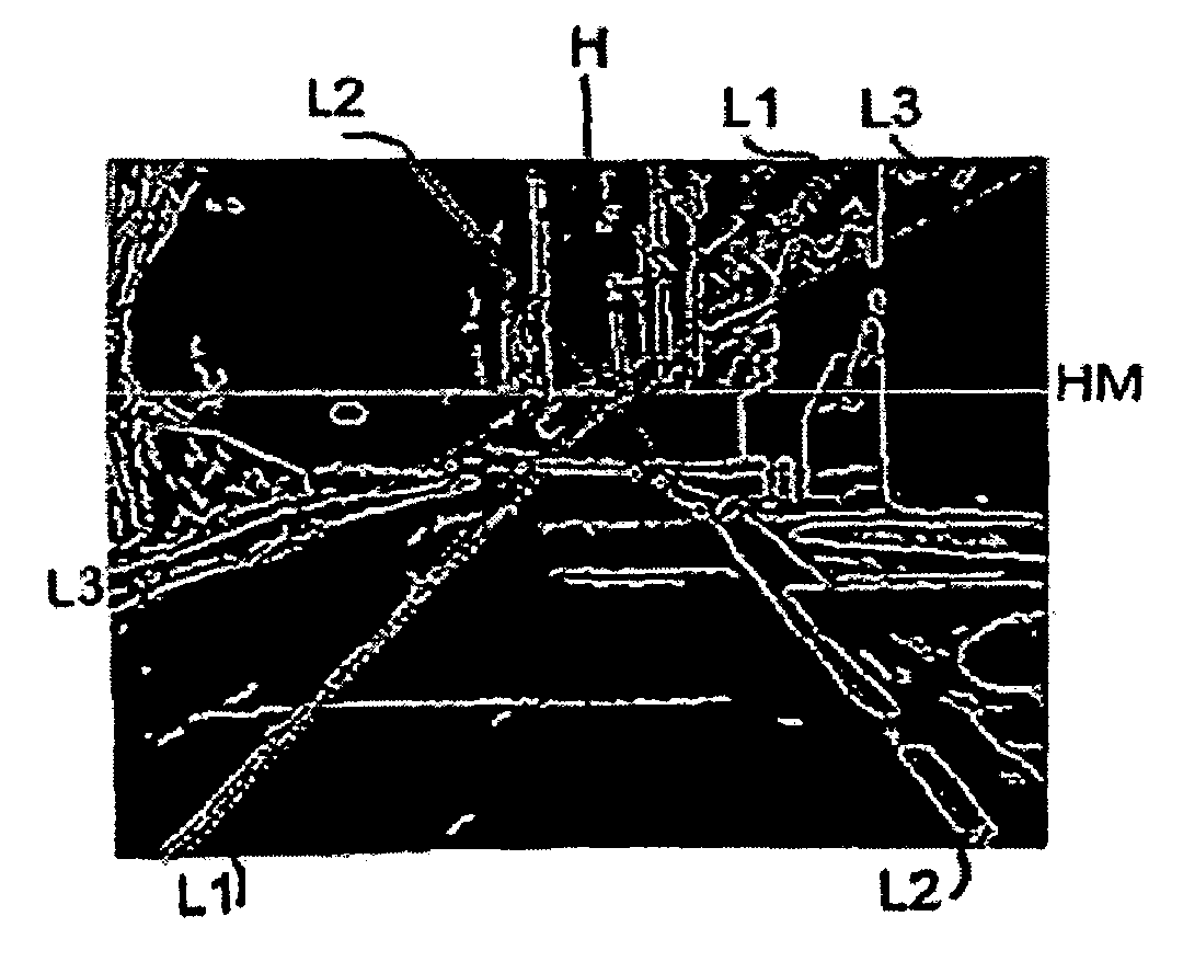
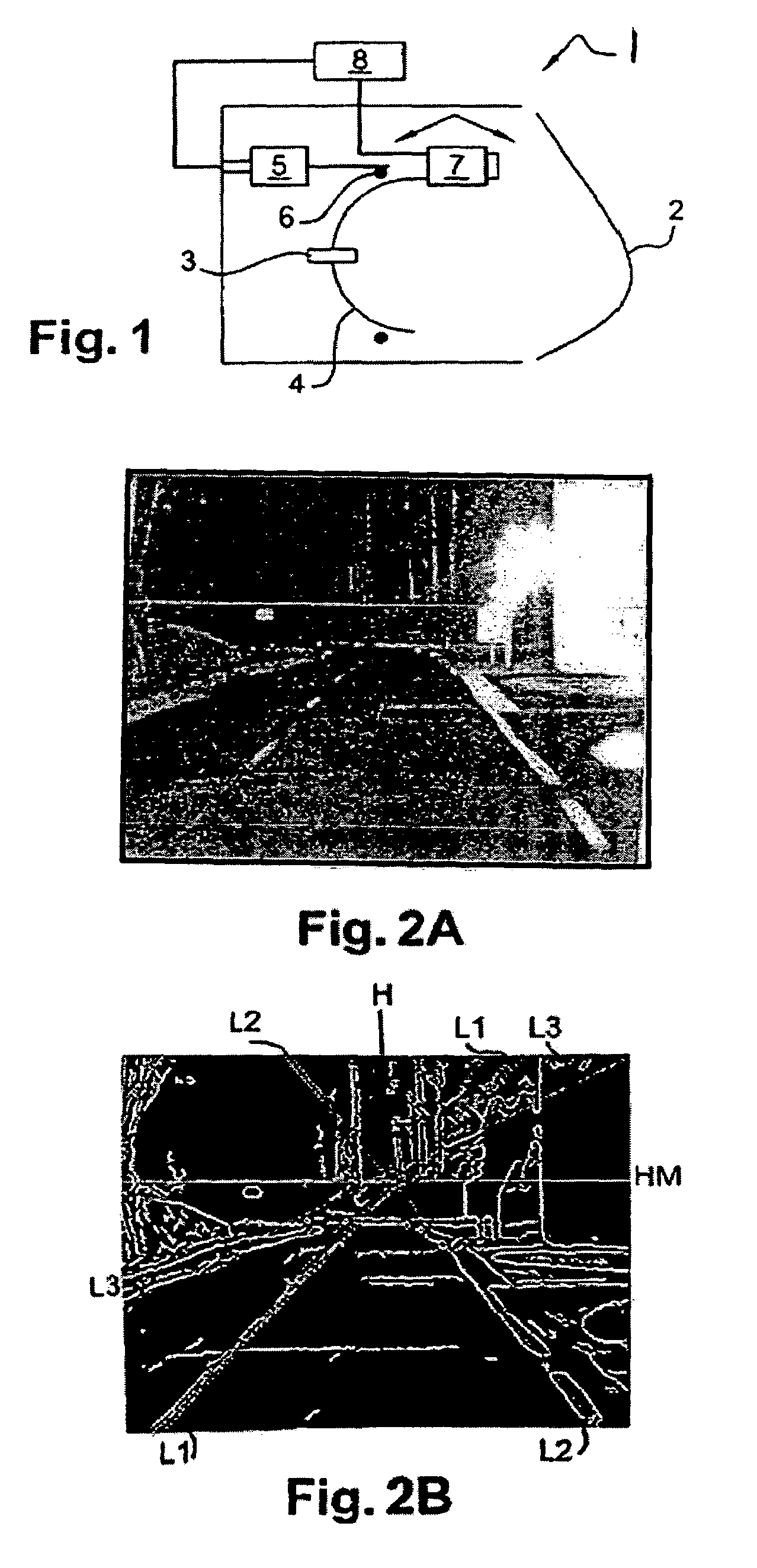
[0023]FIG. 1 shows a dipped beam headlamp of a vehicle, equipped with an orientation control system according to the invention. More precisely, this FIG. 1 shows a headlamp 1 equipped with optics 2 (covering for closing the headlamp, and possibly other parts having an optical role of the lens type) and with a light source 3 mounted on a mobile support 4. This mobile support 4 is the reflector of the headlamp. This reflector 4 is actuated by a motor 5 associated with a rotation device 6, such as a ball joint. Inside the headlamp 1, arrows show the rotary movements of the reflector 4 and, in particular, of the light source 3 secured to the reflector 4. This light source 3 may be a light source that is conventional for a vehicle headlamp. Likewise, the reflector 4, the optics 2, the motor 5 and the rotation device 6 may be elements that are conventional in a vehicle dipped beam headlamp.

[0024]On this reflector 4, there is likewise mounted a camera 7, which is secured to the reflector 4...


PUM


Abstract

A system and method for controlling the in situ orientation of the headlamps of a vehicle, from a camera that is mounted in the headlamp, as a function of the attitude of the vehicle. A camera is secured to a reflector of the headlamp so as to film the road extending in front of the vehicle. An image processing unit processes at least two successive images in order to detennine a measured horizon line of the road scene in front of the vehicle. A setpoint horizon line has been determined beforehand during initial adjustment of the headlamp. The real horizon line is then brought closer to the setpoint horizon line by modifying the orientation of the headlamp, until the distance between the measured line and the setpoint line tends towards zero.

Description

FIELD OF THE INVENTION[0001]The invention relates to a system for controlling the in situ orientation of a vehicle headlamp providing constant lighting of the road, irrespective of the attitude of the vehicle. The invention also relates to a method allowing use of this control system.[0002]The invention finds applications in the field of road-going vehicles such as, for example, cars or heavy goods vehicles. In particular, it finds applications in the field of the projection of light by these vehicles onto the road.PRIOR ART[0003]At present, all road-going vehicles comprise a device for lighting the road, said device being used in particular at night or during bad weather. Conventionally, there are two types of lighting used in motor vehicles: lighting known as “full beam”, which lights up the road as a whole over a long distance, and lighting known as “dipped beam”, which lights up the road over a short distance so as to avoid dazzling the drivers of vehicles that are liable to com...

Claims


Application Information

Patent Timeline
Patent Type & Authority Patents(United States)
IPC IPC(8): B60Q1/04B60Q1/08G03B15/00B60Q1/10B60Q1/115B60Q1/14B60R1/00F21S8/10F21V7/16F21V14/04F21W101/10F21Y101/00G03B17/02
CPCB60Q1/0023B60Q1/10G01M11/068G01M11/062B60Q2300/324B60Q2300/132
Inventor ALBOU, PIERRELELEVE, JOEL
Owner VALEO VISION SA
Why Eureka
Try Eureka