Detection of clogged filter in an HVAC system

a technology of clogging filter and hvac system, which is applied in the direction of heating types, instruments, separation processes, etc., can solve the problems of increasing the load on the fan, filter clogging, and further operation of the fan

Active Publication Date: 2006-01-31
CARRIER CORP
View PDF14 Cites 206 Cited by
  • Summary
  • Abstract
  • Description
  • Claims
  • Application Information

AI Technical Summary

Problems solved by technology

Over time, the filter becomes clogged, and eventually should be replaced.
A clogged filter presents challenges to the further operation of the fan, and increases the load on the fan.
Further, at some point, the filter may become so full that it ceases to allow air flow, which is also undesirable.
However, such systems are based upon assumptions of filter condition, and not on actual filter condition.
Such assumptions can result in the filter being replaced too frequently, or not frequently enough.

Method used


Image

  • Detection of clogged filter in an HVAC system
  • Detection of clogged filter in an HVAC system

Examples


Embodiment Construction

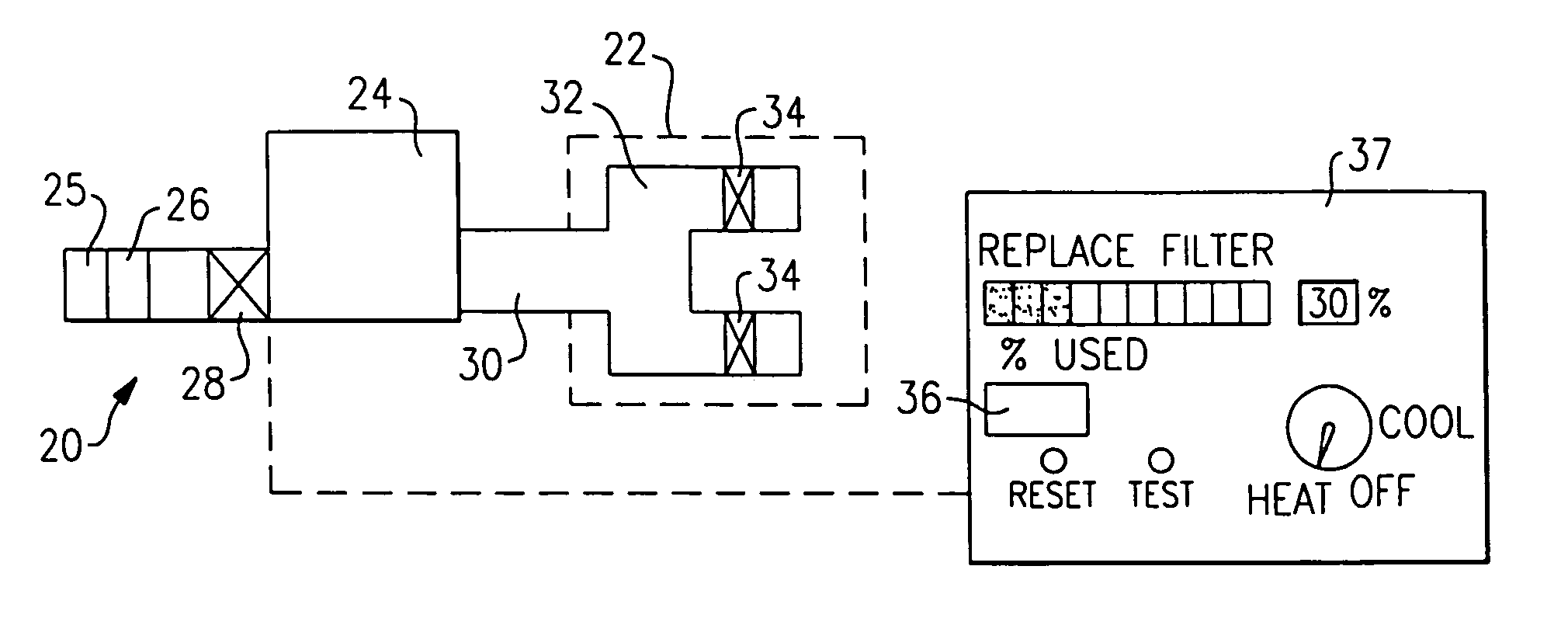
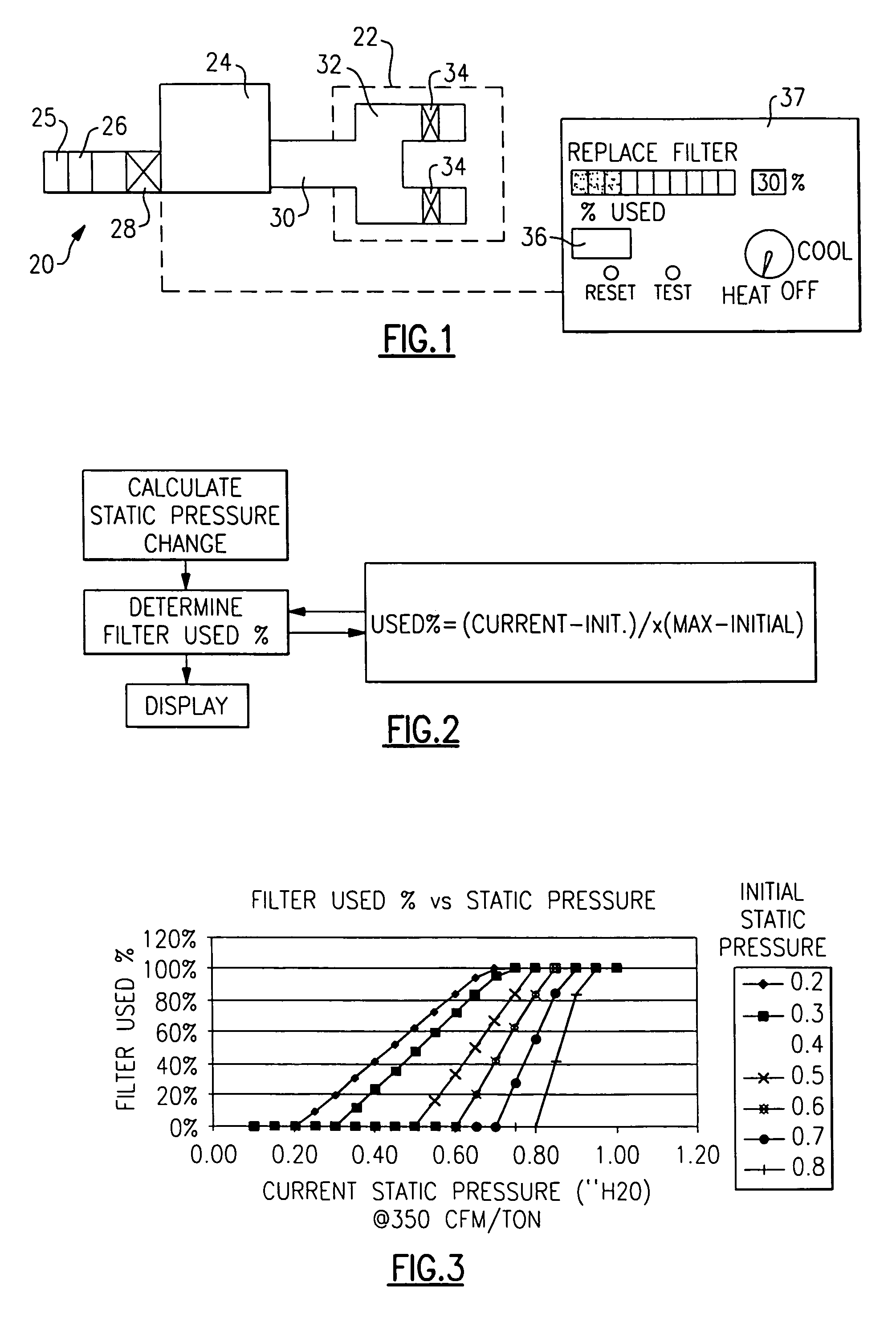
[0012]An HVAC system 20 is illustrated schematically in FIG. 1. As shown, HVAC system 20 operates to heat or cool an environment 22. A component 24, such as a furnace, is provided with air from an inlet air duct 25. Typically, a filter 26 is placed on the inlet air duct 25, and upstream of a fan 28. Fan 28 pulls air through inlet duct 25, filter 26, and through the furnace 24. From the furnace 24, the air is directed into a duct 30, and then into various zones through sub-ducts 32, having dampers 34.

[0013]As mentioned above, it is desirable to periodically replace the filter 26 as it may become clogged. The present invention relates to a method of determining when the filter 26 should be replaced. A control 36, such as a microprocessor, is shown associated with the thermostat 37, and is operable to provide information on the filter 26.

[0014]The present invention relies upon a recognition that static pressure is the sum of pressure drops at three points, namely, through the duct syst...


PUM

PropertyMeasurementUnit
pressuresaaaaaaaaaa
pressureaaaaaaaaaa
static pressureaaaaaaaaaa

Abstract

Static pressures are measured in an HVAC system and utilized to predict the condition of a filter in the HVAC system. As the filter becomes clogged, the static pressure can be expected to increase. Changes in the static pressure are determined periodically, and utilized to predict the condition of the filter. A display provides a user with an indication of the current condition of the filter, and a recommendation to replace the filter once it reaches a predetermined condition.

Description

BACKGROUND OF THE INVENTION[0001]This invention utilizes pressure measurements in an HVAC system to determine when an air filter has been clogged to the point that it should be replaced.[0002]Filters are utilized to provide clean air to an HVAC system for circulation within an environment to be heated or cooled. As is known, the filter is typically placed upstream of a fan, and air is sucked through the filter, with impurities removed from the air.[0003]Over time, the filter becomes clogged, and eventually should be replaced. A clogged filter presents challenges to the further operation of the fan, and increases the load on the fan. Further, at some point, the filter may become so full that it ceases to allow air flow, which is also undesirable.[0004]In the prior art, there have been recommendations for periodic replacement of the filter. As an example, one known thermostat is provided with a signal recommending filter replacement after a period of time since the prior filter replac...

Claims


Application Information

Patent Timeline
Patent Type & Authority Patents(United States)
IPC IPC(8): G05D23/00F24F11/00G05B23/02
CPCB01D46/0086B01D46/446F24F11/0086F24F2011/0093B01D2279/50F24F11/30F24F11/39F24F11/52G05D23/00G05B21/00
Inventor SHAH, RAJENDRA K.
Owner CARRIER CORP
Why Eureka
Try Eureka