Supercharge Your Innovation With Domain-Expert AI Agents!

Lock with clutching function

a technology of locking function and lock, applied in the field of locks, can solve the problems of damage to the internal parts of the door lock,

Inactive Publication Date: 2006-02-07
I TEK METAL MFG
View PDF12 Cites 40 Cited by
  • Summary
  • Abstract
  • Description
  • Claims
  • Application Information

AI Technical Summary

Benefits of technology

"The present invention relates to a lock with a unique mechanism that allows for secure locking and unlocking. The lock includes a case, an inside handle, an outside handle, a first spindle, a second spindle, a first wheel, a second wheel, a first lever, a second lever, and a locking plug. The locking plug is movable between an unblocking position and a blocking position. When in the blocking position, the locking plug presses against the first and second wheels, causing them to move and lock the spindles in place. The locking mechanism is designed to prevent unauthorized access to the lock."

Problems solved by technology

However, the internal parts of the door lock could be damaged if the outside handle is frequently depressed when the user is not aware of the locking state of the lock.
Also, the internal parts of the door lock could be damaged if the outside handle is depressed with a relatively large force when the user is not aware of the locking state of the lock.

Method used


Image

  • Lock with clutching function
  • Lock with clutching function
  • Lock with clutching function

Examples


Embodiment Construction

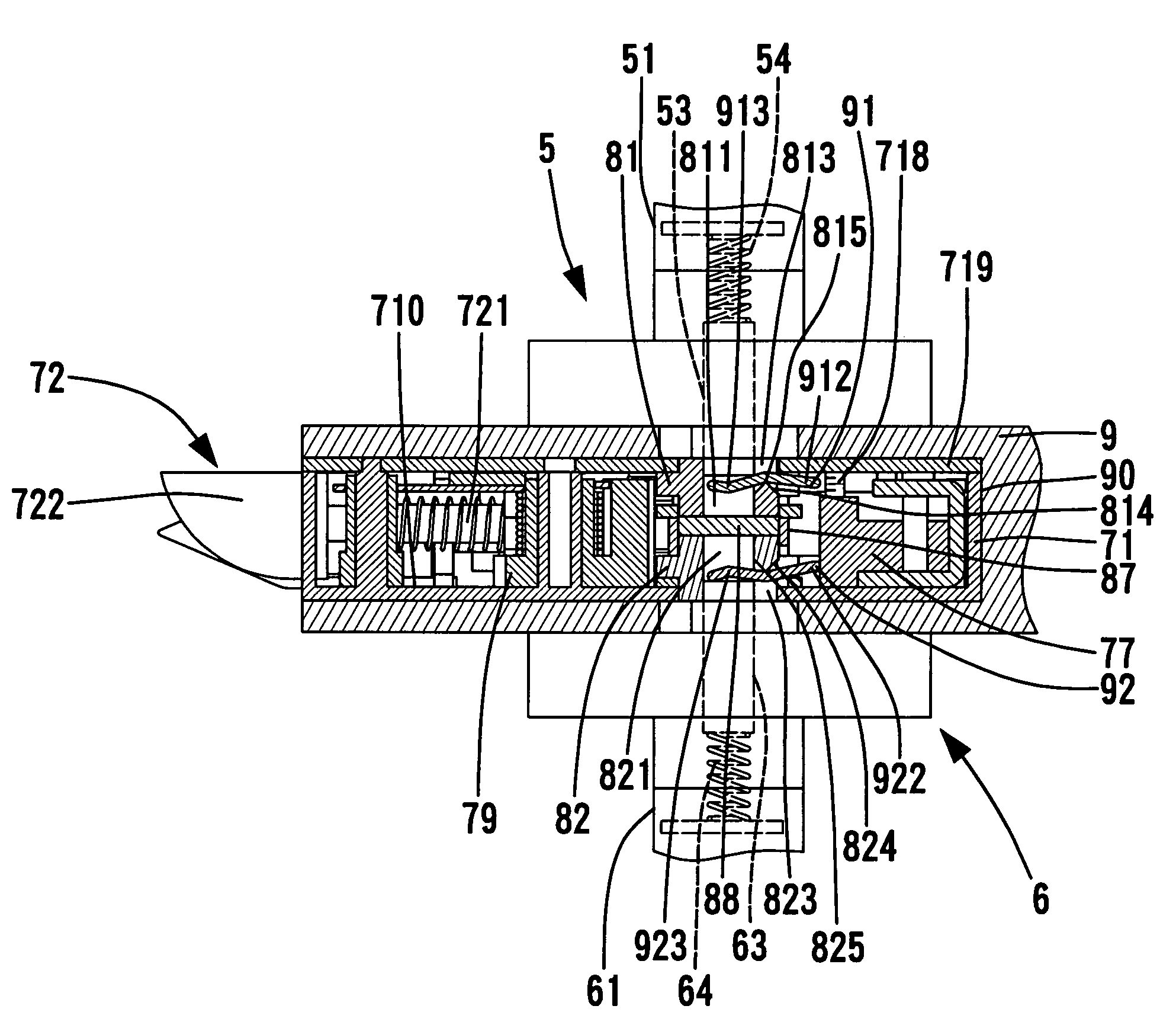
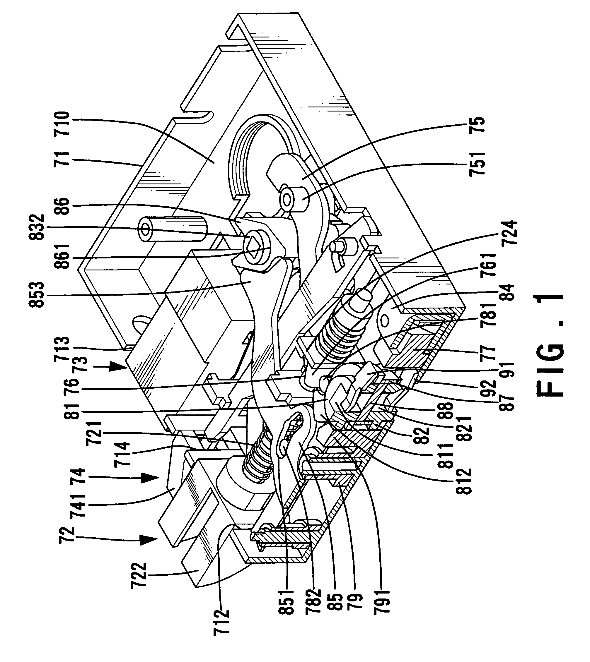
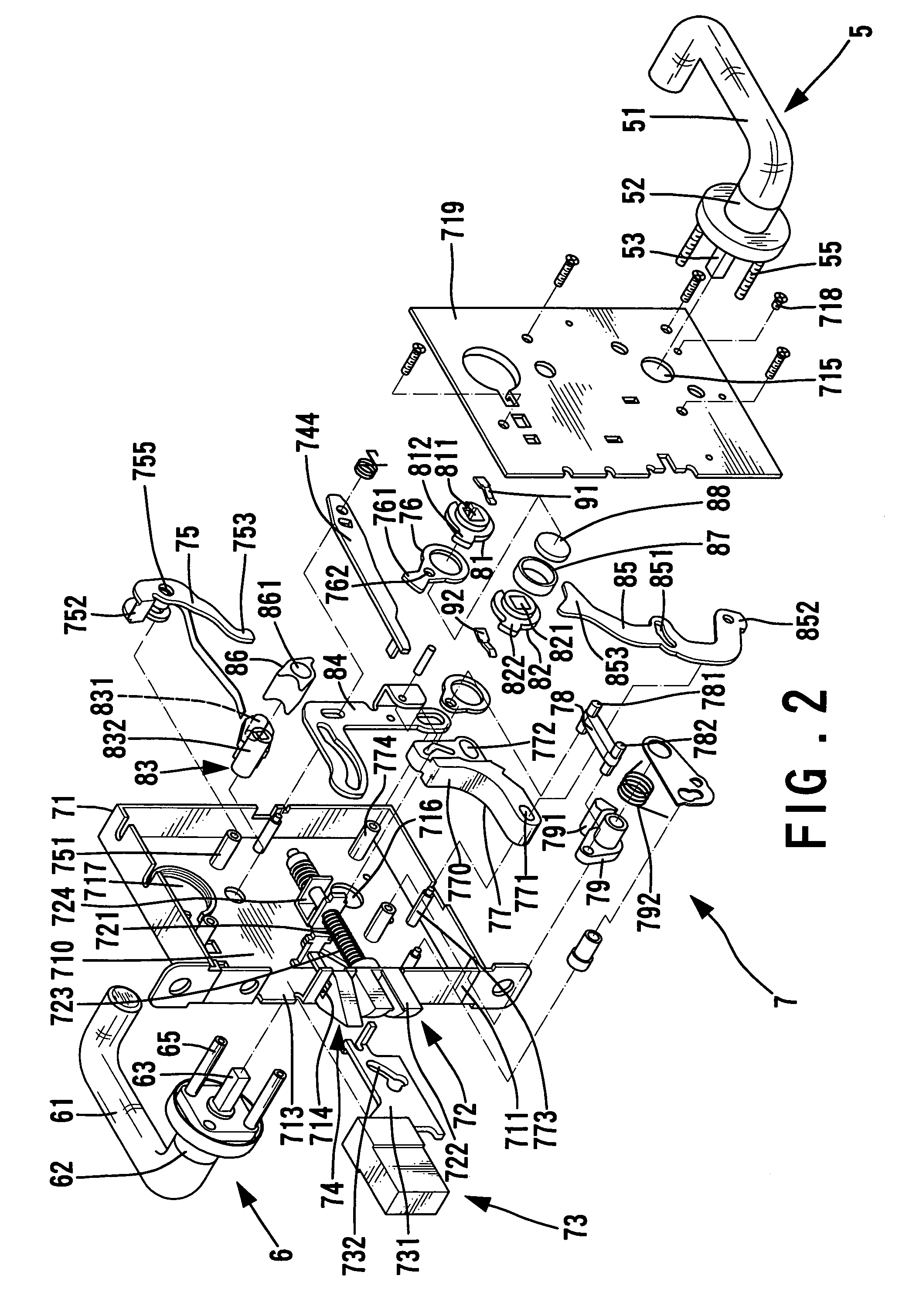
[0048]Referring to FIGS. 1 through 3, a lock in accordance with the present invention comprises an inside handle assembly 5, an outside handle assembly 6, and a body 7 between the inside and outside handle assemblies 5 and 6.

[0049]The inside handle assembly 5 includes an inside handle 51, an inside spindle 53 mounted to an end 52 of the inside handle 51. The outside handle assembly 6 includes an outside handle 61, an outside spindle 63 mounted to an end 62 of the outside handle 61. The inside handle assembly 5 and the outside handle assembly 6 are assembled together and respectively fixed to two sides of the body 7 by bolts 55 and mounting rods 65 with screw holes (not labeled). The inside and outside spindles 53 and 63 are square in this embodiment.

[0050]The body 7 is mounted in a groove or compartment 90 in a door 9 and includes a case 71 and a lid 719 for covering the case 71. The case 71 includes an outer end face 711 having three openings 712 (FIG. 1), 713, and 714 into which a...


PUM


Abstract

A lock includes an inside handle, an outside handle, and a body between the handles. A spindle is mounted to each handle to turn therewith. Two pivotable wheels are mounted in the case and operably connected to the inside and outside spindles and a latch bolt such that turning of either handle causes retraction of the latch bolt. One of the wheels engaging with the outside spindle includes a notch communicated with a through-hole of the wheel. A lever extends through the notch of the wheel and includes an end in the through-hole of the notched wheel. When a locking plug is moved to a blocking position, the end of the lever sways to move the outside spindle out of the through-hole of the notched wheel such that the outside handle turns idly when the outside handle is turned.

Description

BACKGROUND OF THE INVENTION[0001]1. Field of the Invention[0002]The present invention relates to a lock. In particular, the present invention relates to a lock with a clutch function, allowing free rotation of the outer handle when the lock is in a locked state.[0003]2. Description of the Related Art[0004]U.S. Pat. No. 4,583,382 discloses a door lock with a reversible latch assembly with integrated function. The door lock comprises a generally rectangular case, a latch bolt disposed in the case, and a dead bolt disposed in the case. The case includes a front plate for confronting a door frame. A portion of the latch bolt is selectively extensible from the front plate of the case for securing relative movement between the door and the door frame. A portion of the dead bolt is selectively extensible from the front plate of the case for further securing relative movement between the door and the door frame. An outside handle is provided on the outside of a side of the case for selectiv...

Claims


Application Information

Patent Timeline
Patent Type & Authority Patents(United States)
IPC IPC(8): E05B13/00
CPCE05B13/005E05B55/12Y10S292/27Y10T70/5805Y10T70/5416Y10T292/099Y10T70/5496Y10T70/5226
Inventor SHEN, MU-LIN
Owner I TEK METAL MFG
Features
  • R&D
  • Intellectual Property
  • Life Sciences
  • Materials
  • Tech Scout
  • Unparalleled Data Quality
  • Higher Quality Content
  • 60% Fewer Hallucinations
Learn More