Inflatable body armor system

a body armor and inflatable technology, applied in the field of body armor, can solve the problems of increasing the weight and cost of the body armor

Inactive Publication Date: 2006-02-14
THE UNITED STATES OF AMERICA AS REPRESENTED BY THE SECRETARY OF THE NAVY
View PDF5 Cites 59 Cited by
  • Summary
  • Abstract
  • Description
  • Claims
  • Application Information

AI Technical Summary

Benefits of technology

[0005]Accordingly, it is an object of the present invention to provide a body armor system that offers the wearer protection from an incoming projectile.
[0006]Another object of the present invention is to provide a lightweight body armor system.

Problems solved by technology

However, both methods increase the weight and cost of the body armor.

Method used


Image

  • Inflatable body armor system
  • Inflatable body armor system
  • Inflatable body armor system

Examples


Embodiment Construction

[0018]Prior to describing the inflatable body armor system of the present invention, a novel inflatable trajectory altering system will first be described. The trajectory altering system forms the core element for the inflatable body armor system.

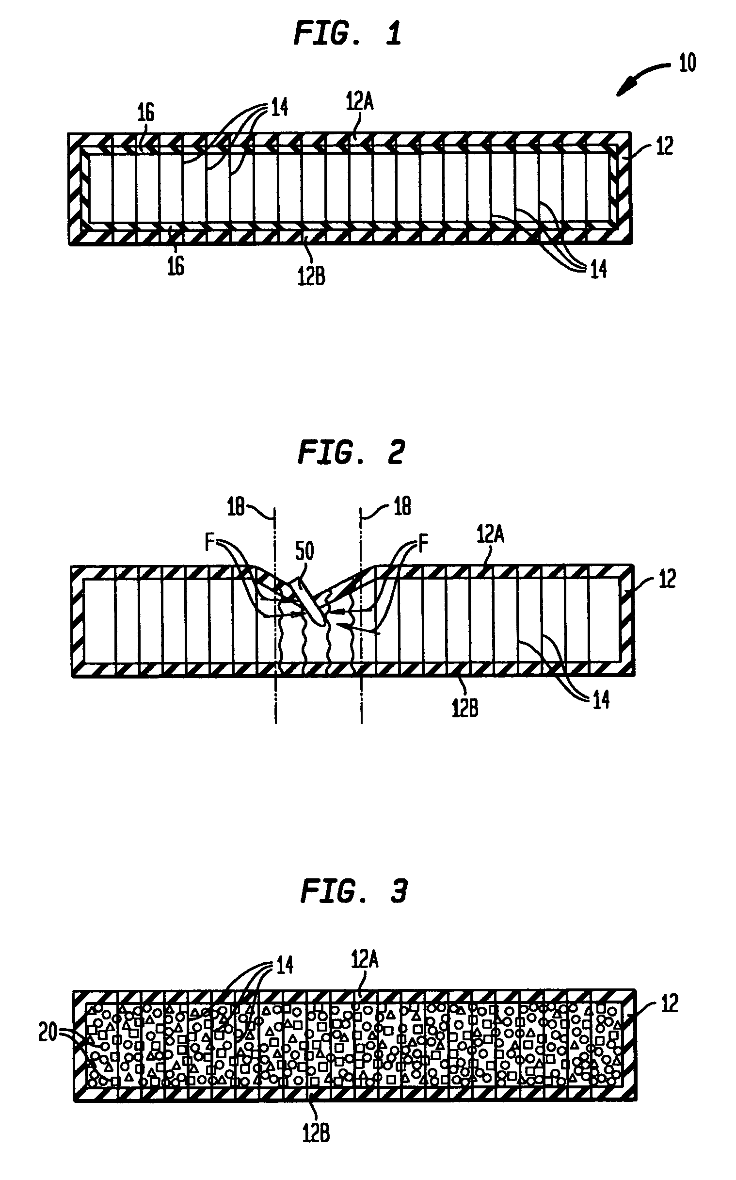
[0019]Referring now to the drawings, and more particularly to FIG. 1, one embodiment of an inflatable trajectory altering system of the present invention is shown in its inflated state and is referenced generally by numeral 10. System 10 has an outer wall structure 12 made from a flexible and fluid-impermeable material that defines a plenum. More specifically, wall structure 12 has major opposing walls 12A and 12B that are spaced apart from one another when the interior volume defined by wall structure 12 is inflated with a lightweight fluid such as air. The means used to inflate wall structure 12 can be any compressed air (or other fluid) inflation system and is not a limitation of the present invention. Inflation of system 10 can occur ju...


PUM

PropertyMeasurementUnit
flexibleaaaaaaaaaa
trajectoryaaaaaaaaaa
anglesaaaaaaaaaa

Abstract

An inflatable body armor system has one or more body armor sections adapted to be worn by a user. Each body armor section includes (i) a inflatable flexible / sealable plenum, (ii) a ballistic armor fabric encasing the plenum, and (iii) a variety of lines, shaped objects and / or fabric sheets dispersed in the plenum to alter the trajectory of a projectile entering the plenum.

Description

ORIGIN OF THE INVENTION[0001]The invention described herein was made in the performance of official duties by employees of the Department of the Navy and may be manufactured, used, licensed by or for the Government for any governmental purpose without payment of any royalties thereon.CROSS-REFERENCE TO RELATED PATENT APPLICATIONS[0002]This patent application is co-pending with one related patent application entitled “INFLATABLE TRAJECTORY ALTERING AND BLAST ENERGY ABSORPTION SYSTEM” (Navy Case No. 96127) by the same inventors as this patent application.FIELD OF THE INVENTION[0003]The invention relates generally to body armor, and more particularly to an inflatable body armor system that alters a projectile's trajectory as the projectile passes through an inflated plenum.BACKGROUND OF THE INVENTION[0004]In today's world, police and military forces frequently wear some form of body armor in order to reduce the threat of severe injury or death due to an incoming projectile. Current bod...

Claims


Application Information

Patent Timeline
Patent Type & Authority Patents(United States)
IPC IPC(8): B65B1/04
CPCF41H1/02F41H5/0435F41H5/0492F41H5/0485Y10S428/911Y10S2/03
Inventor GARCIA, FELIPEWOODALL, ROBERTDOYLE, CHRISTOPHERREITMEYER, GREG
Owner THE UNITED STATES OF AMERICA AS REPRESENTED BY THE SECRETARY OF THE NAVY
Why Eureka
Try Eureka