
Pivotable strap-buckle assembly

a technology of straps and buckles, applied in the field of buckles, can solve the problems of increasing the attendant manufacturing cost, reducing the manufacturer's throughput of the sport-goggles assembly, and unable to ship the straps in pieces to the retailer

Inactive Publication Date: 2006-02-21
SMITH OPTICS
View PDF44 Cites 34 Cited by
  • Summary
  • Abstract
  • Description
  • Claims
  • Application Information

AI Technical Summary

Benefits of technology

The present invention is about buckle assemblies with a pivotable member mounted within a frame. The buckle can be attached to a strap and is suitable for use in sport goggles or other sports equipment. The technical effects of this invention include improved comfort, adjustability, and durability. The straps can be made elastic and the buckle frame can have a flange for added strength. Additionally, the invention allows for the straps to be connected to each other or to a third strap, providing more flexibility in the assembly.

Problems solved by technology

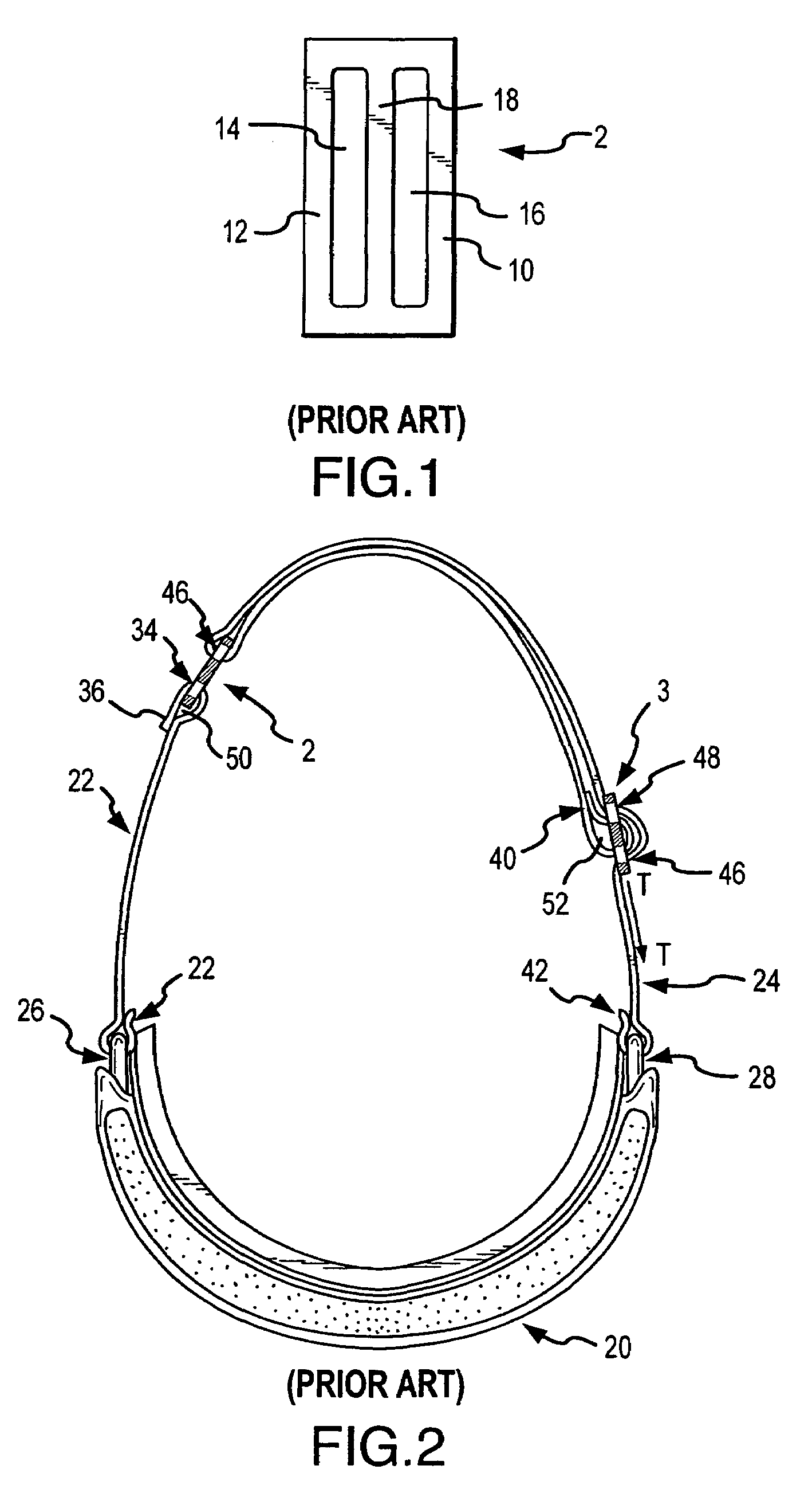
The buckle and strap assembly shown in FIG. 2 works adequately to facilitate lengthening and shortening of the assembly, but it is not without problems.
The sewing step is a bottleneck in the manufacturing process since the sewing is not performed by an automated process.
Sport goggles having sewn straps can not be shipped to the retailer in pieces, and must be fully assembled at the factory prior to shipment.
Thus, performing this step by hand decreases the manufacturer's throughput of the sport-goggles assembly, while increasing the attendant manufacturing costs.
The end user also encounters problems with sport-goggles assemblies having sewn straps.
For example, buckles cannot be replaced by the user without specialized equipment, and are typically returned to the factory for repair.
Because the strap is sewn, the buckle cannot be replaced without removing the stitches, removing the buckle, and re-sewing the strap to secure a new buckle.
As such, sport-goggles users can not replace a damaged buckle without significant difficulty, expense, and delay.
As previously described, the sport-goggles assembly as shown in FIG. 2 may not be disassembled and reassembled without specialized equipment and substantial effort.
Using the sport-goggles assembly shown in FIG. 2, it is difficult to quickly and easily provide additional strap length if a user should desire to use a particular sport-goggles assembly in association with a helmet.

Method used


Image

  • Pivotable strap-buckle assembly
  • Pivotable strap-buckle assembly
  • Pivotable strap-buckle assembly

Examples


Embodiment Construction

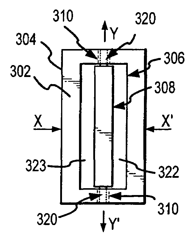
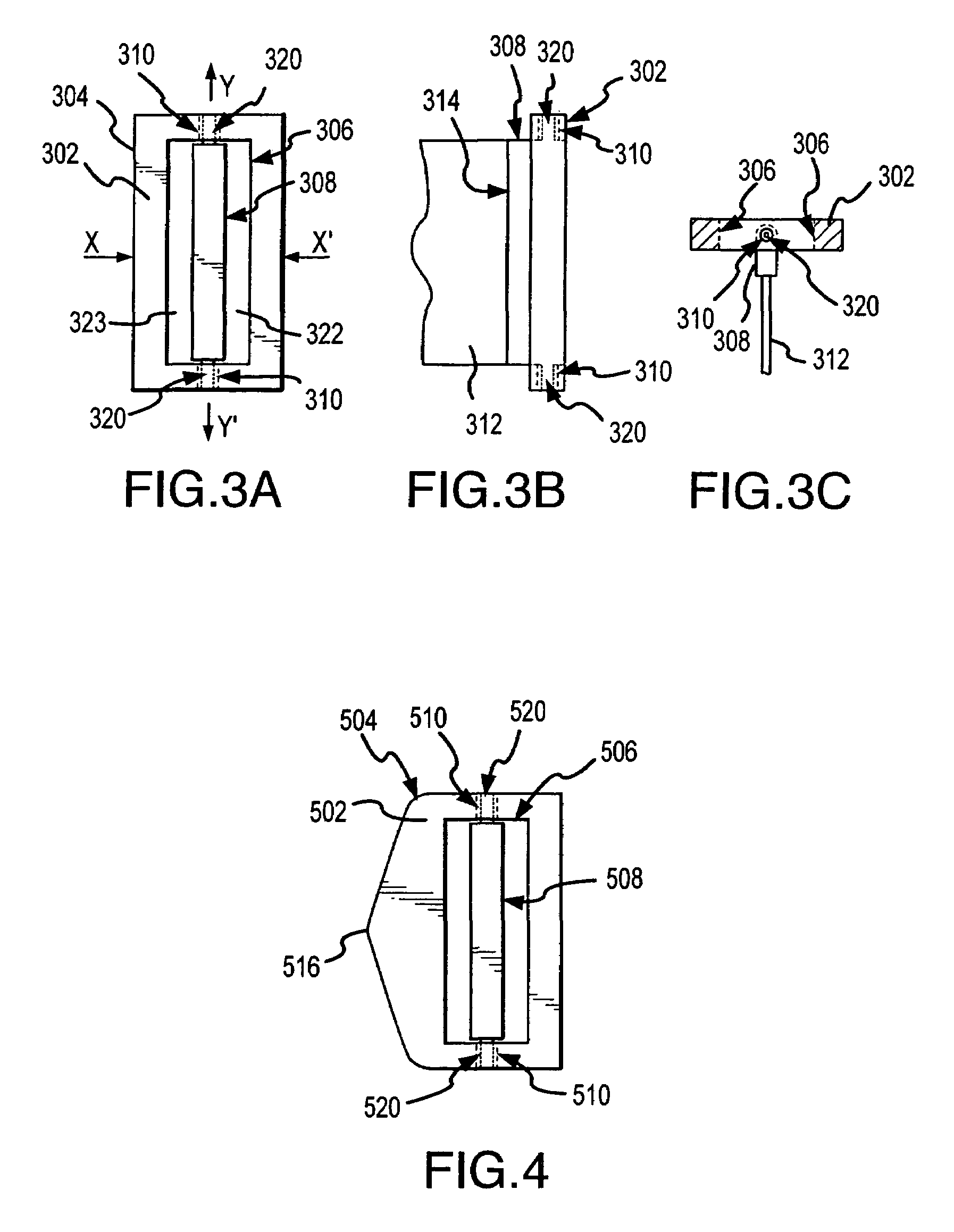
[0026]The present invention is generally directed to a buckle apparatus for securing and adjusting the length of a strap and to a sport goggle using the buckle. More particularly, the present invention is directed to a buckle apparatus for use with sport goggles. Many of the specific details of certain embodiments of the invention are presented in the following description and in FIGS. 3–8 to provide a thorough understanding of such embodiments. One skilled in the art will understand, however, that the present invention may have additional embodiments, or that the present invention may be practiced without several of the details described in the following description. For example, one skilled in the art will understand that in the following discussion the buckle is described as securing sport goggles to the user during operation, but the buckle may be used to secure any object suitable for attachment to a strap.

[0027]FIGS. 3A, 3B and 3C are a plan, front and side view, respectively,...


PUM


Abstract

This invention is directed towards an apparatus for securing and adjusting a strap. More particularly, the present invention is directed towards a buckle assembly having a pivotable member pivotably attached to opposed regions of the buckle frame. In one embodiment, a sport-goggle assembly has a pivotable buckle assembly attached to one end of a strap. In another embodiment, a sport-goggle assembly has a pivotable buckle assembly attached to each of the two straps. In other embodiments, the pivotable buckle assembly can be used in association with a strap-lengthening member.

Description

CROSS-REFERENCE TO RELATED APPLICATION[0001]This application is a continuation of U.S. patent application Ser. No. 10 / 043,952, filed Jan. 9, 2002, now U.S. Pat. No. 6,826,785.TECHNICAL FIELD[0002]This invention relates generally to buckles, and more particularly, to buckle assemblies for use in association with straps.BACKGROUND OF THE INVENTION[0003]Individuals often wear goggles to protect their eyes or to improve their vision when participating in a sport or a recreational activity, such as skiing, motorcycle racing or snowmobiling. During use, a strap holds the goggles in place on the wearer's head. The strap length is typically adjusted and held securely in place by use of a buckle.[0004]FIG. 1 shows a buckle configuration typically used to secure and adjust the length of a strap commonly used with sport goggles. The buckle 2 is unitary, and includes two slots 14, 16 that are bordered by sides 10, 12 and a center bar 18. The slots 14, 16 are sized to receive a strap (not shown)...

Claims


Application Information

Patent Timeline
Patent Type & Authority Patents(United States)
IPC IPC(8): A61D9/02A44B11/12
CPCA44B11/12Y10T24/4016Y10T24/40
Inventor MCNEAL, JOSEPH ROSS
Owner SMITH OPTICS
Learn More