Multiple head worklight

a worklight and head technology, applied in the field of worklights, can solve the problem that none of them can illuminate a circular area

Inactive Publication Date: 2006-02-21
COLEMAN CABLE INC
View PDF3 Cites 46 Cited by
  • Summary
  • Abstract
  • Description
  • Claims
  • Application Information

AI Technical Summary

Benefits of technology

[0010]These and other objects of the present invention are met by a portable worklight disclosed herein that includes a triangular-shaped base with three dual light heads attached to the base's three legs. Each light head includes two diagonally aligned light cavities separated by a vertically aligned transversely aligned partition. Mounted inside each light cavity is a longitudinally aligned halogen bulb. Located behind the halogen bulb is an optional concave reflective shield. Mounted over the front face of each light cavity is an optional glass plate designed to protect the halogen bulb. A chevron-shaped face frame is disposed over the two faces on each light head and used to hold and protect the two glass plates mounted thereon. Also attached to the rear surface on each light head, is a handle that allows each light head to be independently aimed.
[0011]Each light head is mounted on a u-shaped frame that holds and elevates the light head above the base. The u-shaped frame is rotatably mounted to the base, which enables the light head to rotate side-to-side in an approximately 80 degrees arc. Each light head is rotatably mounted between two vertical side members on the u-shaped frame so that it may also be tilted upward and downward approximately 45 degrees. Each light head also includes a separate ON-OFF switch that allows the user to independently control the operation of the two halogen bulbs in each light head.

Problems solved by technology

Unfortunately, this requires multiple worklights spaced apart in the work area each with their own use of several extension cords that can be easily tripped over by workers.
While most multiple head worklights are adjustable so that the heads may be aimed in different directions, none of them can illuminate a circular area.

Method used


Image

  • Multiple head worklight
  • Multiple head worklight
  • Multiple head worklight

Examples


Embodiment Construction

)

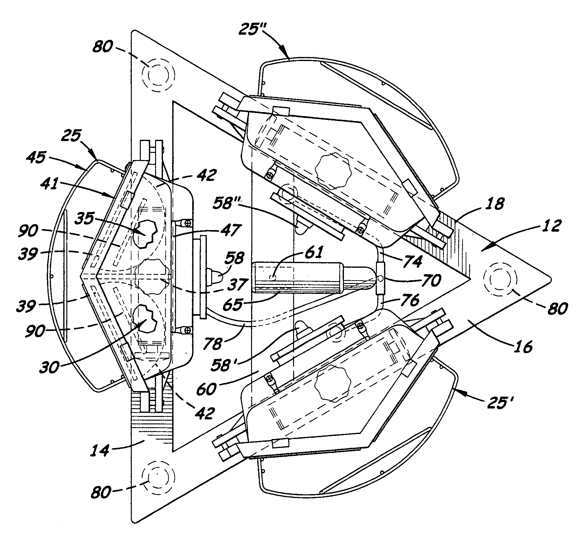
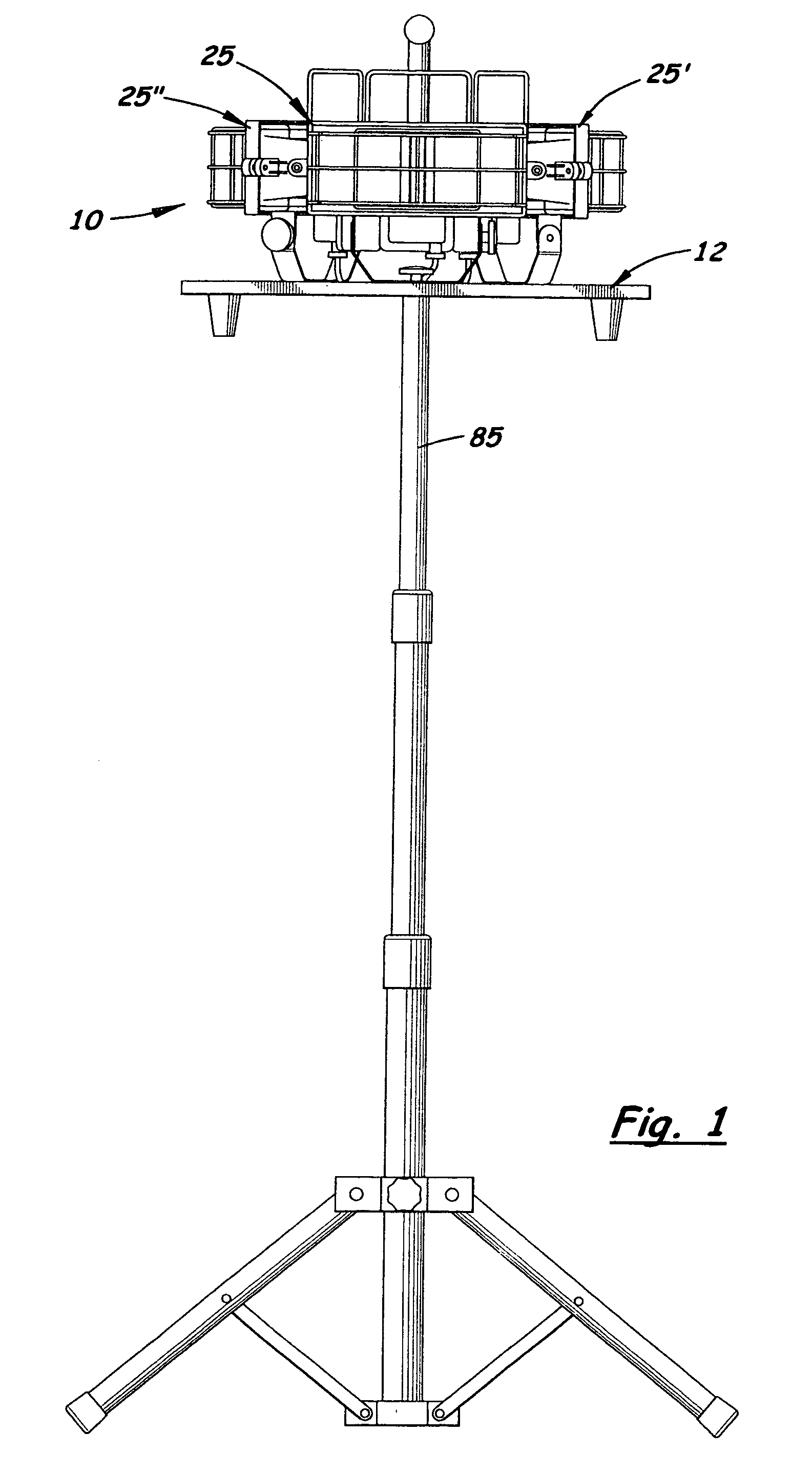
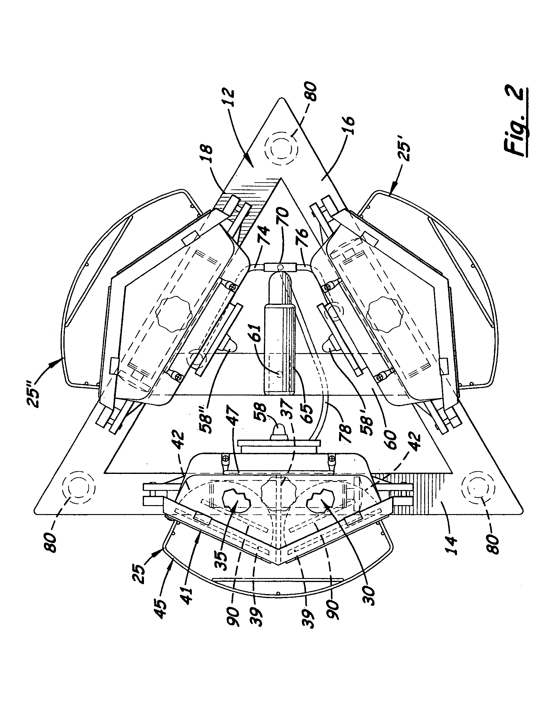
[0021]There is shown in the accompanying FIGS. 1–7 a portable worklight, generally referenced as 10 that includes a triangular-shaped base 12 with three dual bulb light heads 25, 25′, 25″ attached thereto. The base 12 includes three side members 14, 16, 18 welded together at their opposite ends. Each light head 25 includes two diagonally aligned light cavities 30, 35 separated by a partition 37. The light cavities 30, 35 are diagonally aligned approximately 40 degrees from the center of the light head. Mounted inside each light cavity 30, 35 is a longitudinally aligned halogen bulb 90. Located behind the halogen bulb 90 is a concave reflective shield 42. Mounted over the front face of each light cavity 30, 35 is a glass plate 39 designed to protect the halogen bulb 90. A chevron-shaped face frame 41 is used to hold the two glass plates 39, 39′ in place on the light head 25 and over the two cavities 30, 35 respectively. Extending transversely over the two plates 39, 39′ is an option...


PUM


Abstract

A portable worklight designed to illuminate a 360 degree area. The worklight includes a triangular-shaped base with three side members. Mounted on each side member is a rotating and pivoting light head that includes two diagonally aligned light cavities. Mounted inside each light cavity is a horizontally aligned halogen bulb with a concave reflective shield mounted behind the bulb. Mounted over the front face of each light cavity is a glass plate and a chevron-shaped frame. Attached to the rear surface on each worklight includes a handle. Each light head is mounted on a rotating U-shaped bracket that allows the head to rotate upward and downward approximately 45 degrees. The bracket is also able to rotate 360 degrees over the side member. Each light head also includes a separately operated ON-OFF switch that controls the operation of the halogen bulbs contained therein.

Description

[0001]This utility patent application claims the benefit of provisional patent application (Ser. No. 60 / 493,962) filed on Aug. 8, 2003.BACKGROUND OF THE INVENTION[0002]1. Field of the Invention[0003]This invention pertains to worklights and more particularly to worklights designed to illuminate a wide area.[0004]2. Description of the Related Art[0005]When working in a dark work area, it is sometimes desirable to illuminate a wide area with few shadows. Typically, this requires the use of several worklights aimed at different work areas that slightly overlap. Unfortunately, this requires multiple worklights spaced apart in the work area each with their own use of several extension cords that can be easily tripped over by workers.[0006]Multiple head worklights mounted longitudinally on a rigid bar are relatively common. All of them include legs that allow them to be placed upright on the ground. Some multiple head worklights include a telescopic pole that allows the worklights to be e...

Claims


Application Information

Patent Timeline
Patent Type & Authority Patents(United States)
IPC IPC(8): F21S13/14F21L14/04F21S8/00F21S8/08F21V21/22F21V21/30
CPCF21S8/08F21V21/30F21L14/04F21W2131/1005F21W2131/10F21V21/22
Inventor LEEN, MONTE A.
Owner COLEMAN CABLE INC
Why Eureka
Try Eureka