Post mount assembly

Active Publication Date: 2006-02-28
CAMINOVERDE II
View PDF27 Cites 62 Cited by
  • Summary
  • Abstract
  • Description
  • Claims
  • Application Information

AI Technical Summary

Problems solved by technology

Many known post mount systems, however, are prone to loosening, tilting and/or rotation due to wind loading, temperature changes or impact on

Method used


Image

  • Post mount assembly
  • Post mount assembly
  • Post mount assembly

Examples


Embodiment Construction

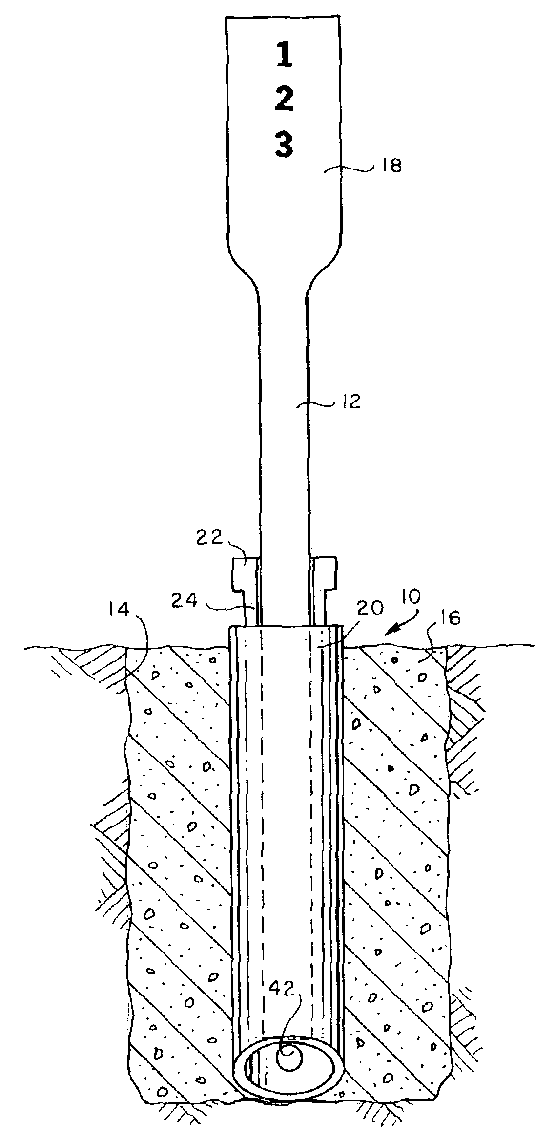
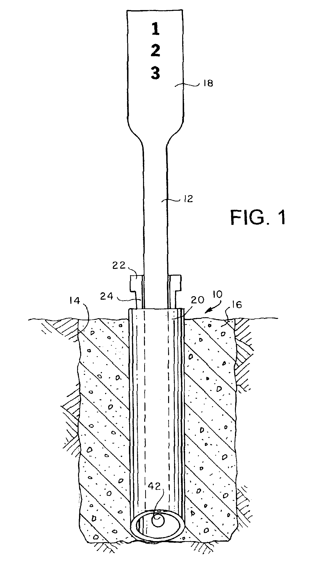
[0018]In its simplest aspect, the post mount assembly of the present invention includes a socket 20 in the hole 14, concrete 16 in the annular space between the interior walls of the hole 14 and the exterior of the socket 20, a post 12 in the socket 20, and a wedge member 22 having a tapered portion 24 filling a gap between the socket 20 and the post 12.

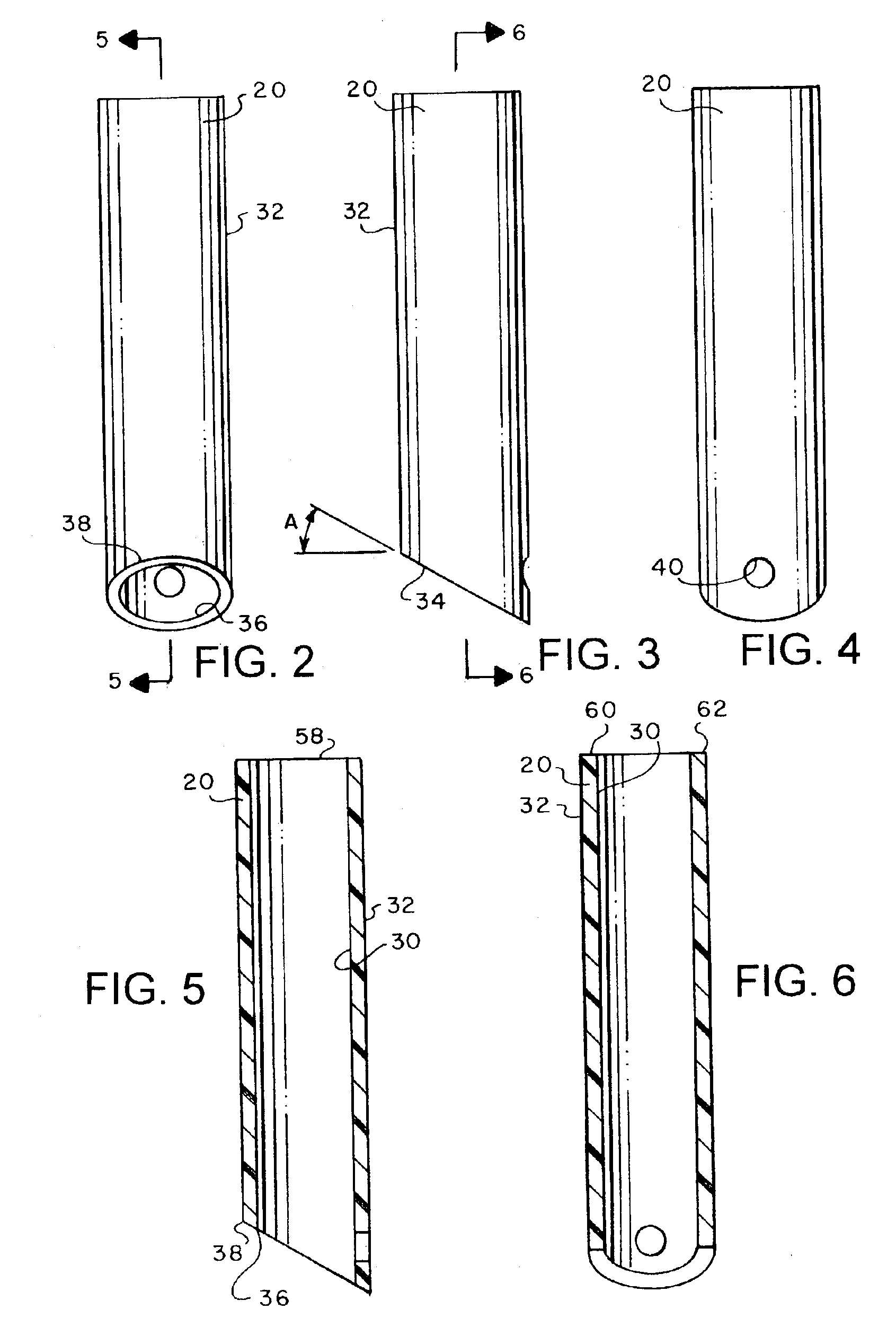
[0019]Socket 20 is a cylindrical tube with coaxial, parallel inner and outer walls 30, 32 respectively. Socket 20 has a lower end 34 at an oblique angle “A” to the inner and outer walls 30, 32. Lower end 34 of the socket 20 has inner and outer elliptical edges, 36, 38 respectively. Preferably, the oblique angle “A” of the socket lower end 34 is about thirty degrees from perpendicular to the inner and outer walls 30, 32.

[0020]Socket 20 has walls 40 defining a locking port 42. Preferably, locking port 42 is defined in the lower end 34 of the socket 20 with cylindrical, horizontal walls 40. As best shown in FIG. 7, the uppermost portion...


PUM


Abstract

A post and post mount assembly in a hole in the ground has a socket in the hole, concrete in the annular space between the interior walls of the hole and the exterior of the socket, a post in the socket, a wedge member having a tapered portion filling a gap between the socket and the post.

Description

BACKGROUND OF INVENTION[0001]The present invention relates in general to sign post mounts. More specifically, but without restriction to the particular use which is shown and described, this invention relates to sign post support mounts that incorporate tubular sockets and driven-in fasteners.[0002]Sign post mounts are known in the art. Conventional sign post mounts are a tubular device that is fixed in concrete or driven into the ground to receive the sign post and mount the sign post in an upright position. A driven-in fastener is often used to attach the sign post to the in-ground post mount to secure the sign post in the upright position. Many known post mount systems, however, are prone to loosening, tilting and / or rotation due to wind loading, temperature changes or impact on the sign post. Another known problem with existing post mounts is the hazard that arises from use of sharp and abruptly-edged metal components. Accordingly, there is a need for an improved post mount for ...

Claims


Application Information

Patent Timeline
IPC IPC(8): E02D27/42E04H12/22H01B1/24H01C17/065
CPCE04H12/2269H01C17/06586H01B1/24
Inventor RIKER, RONALD D.
Owner CAMINOVERDE II
Why Eureka
Try Eureka