
Eureka
For R&D, Eureka makes reading and utilizing patents & technical documents easy.
Eureka AIR
Designed for self-driven R&D workflows. Generate viable solutions, solve complex R&D challenges, empower your innovation with AI.

Eureka Materials
Designed for material experts only. Revolutionize your material R&D, from search, analyze, to developing new materials.

TechResearch
Generate reliable direction feasibility study reports for your R&D in just a few steps.

TechSeek
Discover and master advanced knowledge NOW. Basics, ideas, possibilities, all at once.

TechMind
As an expert in R&D Theories, TechMind can generates customized viable solutions instantly.

TechRisk
Analyze your overall solution with one click, know your potential R&D risks in advance.

TechMonitor
Get weekly tech updates, stay abreast of the latest tech innovations and key insights.
Cable closure
- Summary
- Abstract
- Description
- Claims
- Application Information
AI Technical Summary
Problems solved by technology
Method used
Image

Examples
Embodiment Construction
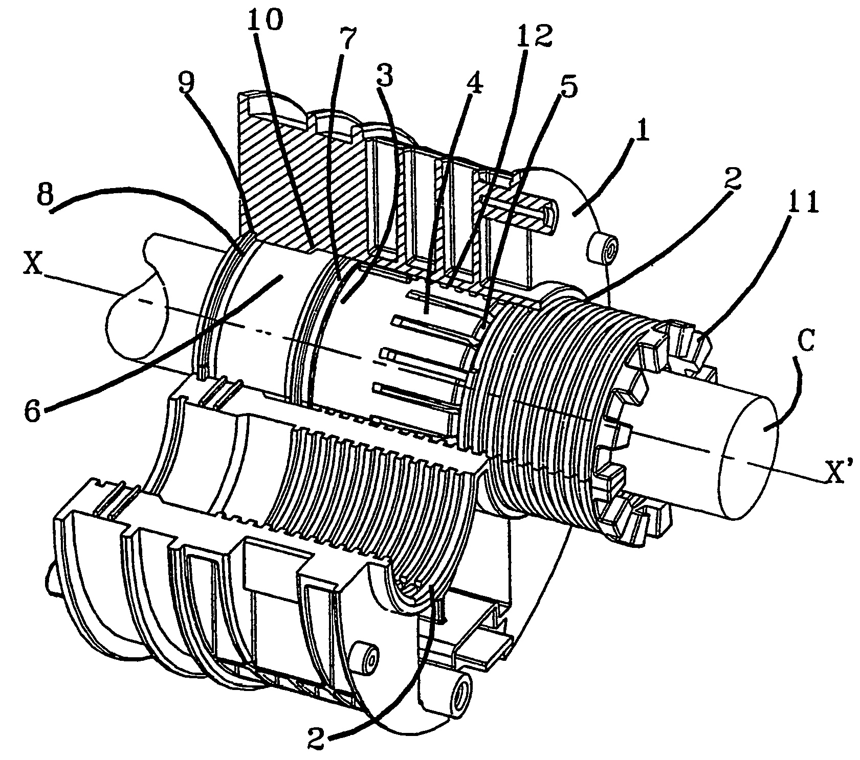
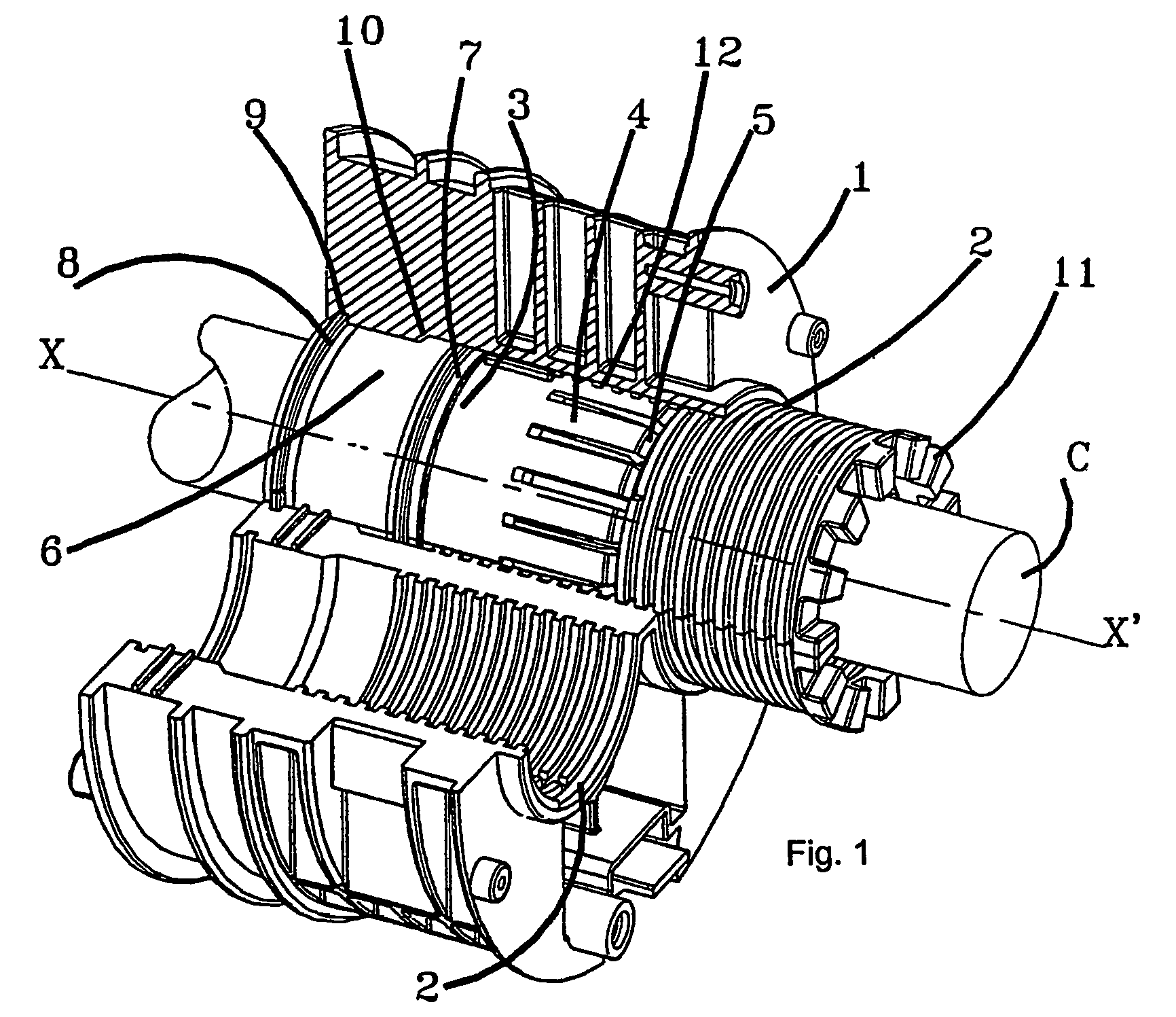
[0018]The splice protection sleeve flange shown in FIG. 1 comprises a flange body 1 defining two passages 2 for a cable C. The flange includes, as means for mechanically clamping the cable C, an annulus 3 extended by bars 4 uniformly spaced around the perimeter. These bars are resilient and each of them terminates in a claw 5 facing inwards and intended, when the bar is pushed back towards the axis XX′ of the passage, to penetrate the cable C and mechanically clamp it properly.
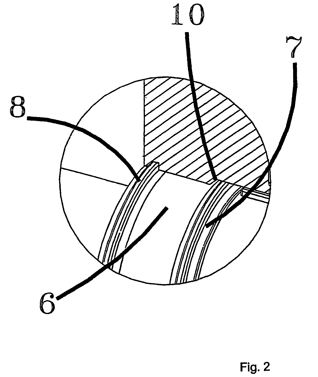
[0019]Further inside the sleeve, a seal 6, for example made of an elastomer or of what is called a gel, is interposed between a moveable ring 7 and a fixed ring 8. The ring 8 is immobilized by penetrating a groove 9 made on the inner face of the body 1. The cable C is slipped between the two rings 7, 8. The ring 7 can move along the axis XX′ as far as a stop 10 (FIG. 2) made on the body 1.
[0020]A frustoconical threaded slide 11 is screwed into a tapping 12 in the body when it is slipped into the passage 2 via ...
PUM
 Abstract
Description
Claims
Application Information
 - R&D Engineer
- R&D Manager
- IP Professional
- Industry Leading Data Capabilities
- Powerful AI technology
- Patent DNA Extraction
Browse by: Latest US Patents, China's latest patents, Technical Efficacy Thesaurus, Application Domain, Technology Topic, Popular Technical Reports.
© 2024 PatSnap. All rights reserved.Legal|Privacy policy|Modern Slavery Act Transparency Statement|Sitemap|About US| Contact US: help@patsnap.com