Stent with micro-latching hinge joints

a hinge joint and stent technology, applied in the field of medical devices, can solve the problems of minimal elastic recovery, limited material selection, and typical elastic recoil of some components

Inactive Publication Date: 2006-11-28
MIRUS LLC
View PDF7 Cites 193 Cited by
  • Summary
  • Abstract
  • Description
  • Claims
  • Application Information

AI Technical Summary

Benefits of technology

[0016]The present invention relates to a radially expandable stent for use in an artery or any other body lumen. It is comprised of radially expandable structural members with micro latches incorporated in their joints. The micro latches allow growth of the angle between the structural members in the direction that results in radial expansion of the structure, but restricts change of the angle between the structural members in the reverse direction.

Problems solved by technology

However one disadvantage to balloon-expandable stents is that there is typically some component of elastic recoil after expansion as long as the mechanism for change between the crimped state to the expanded state is through deformation of the structural elements.
These factors vary from stent to stent and situation to situation, presenting a challenge for the practitioner to achieve the desired outcome in repeatable manner.
For this reason, the material selection is limited to a material that plastically deforms at relatively low strain levels, with a minimal degree of elastic recovery.
Furthermore, no specialized micro-fabrication method is specified in order to create the latching elements.
There are several undesirable characteristics that result from these important differences.
In practice, one of the general drawbacks to stent-latching mechanisms has been that the latching mechanisms themselves add an additional element that provides additional bulk to the device.
For this reason the inclusion of a conventional latch presents reduced flexibility and a larger undeployed profile, i.e., diameter.
This means that the puncture site to the vessel for introducing the stent must be larger as well, leading to longer post-procedure patient recovery times.
Another drawback to standard stent-latching mechanisms has been that the sizing increment is not continuous.

Method used


Image

  • Stent with micro-latching hinge joints
  • Stent with micro-latching hinge joints
  • Stent with micro-latching hinge joints

Examples


Embodiment Construction

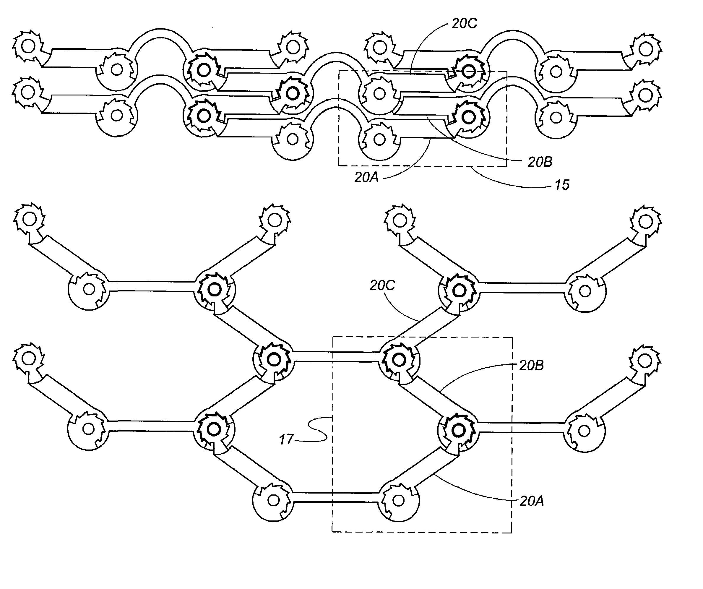
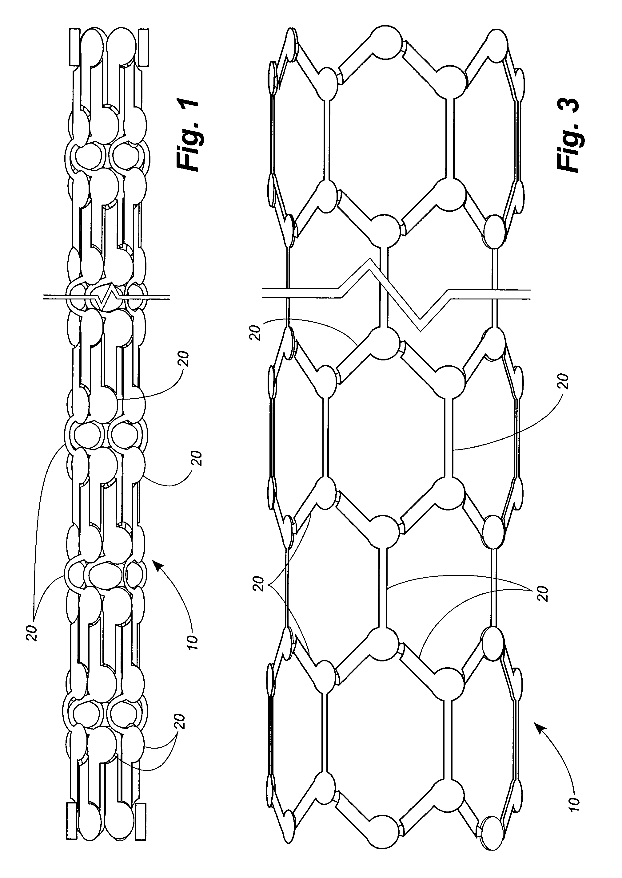
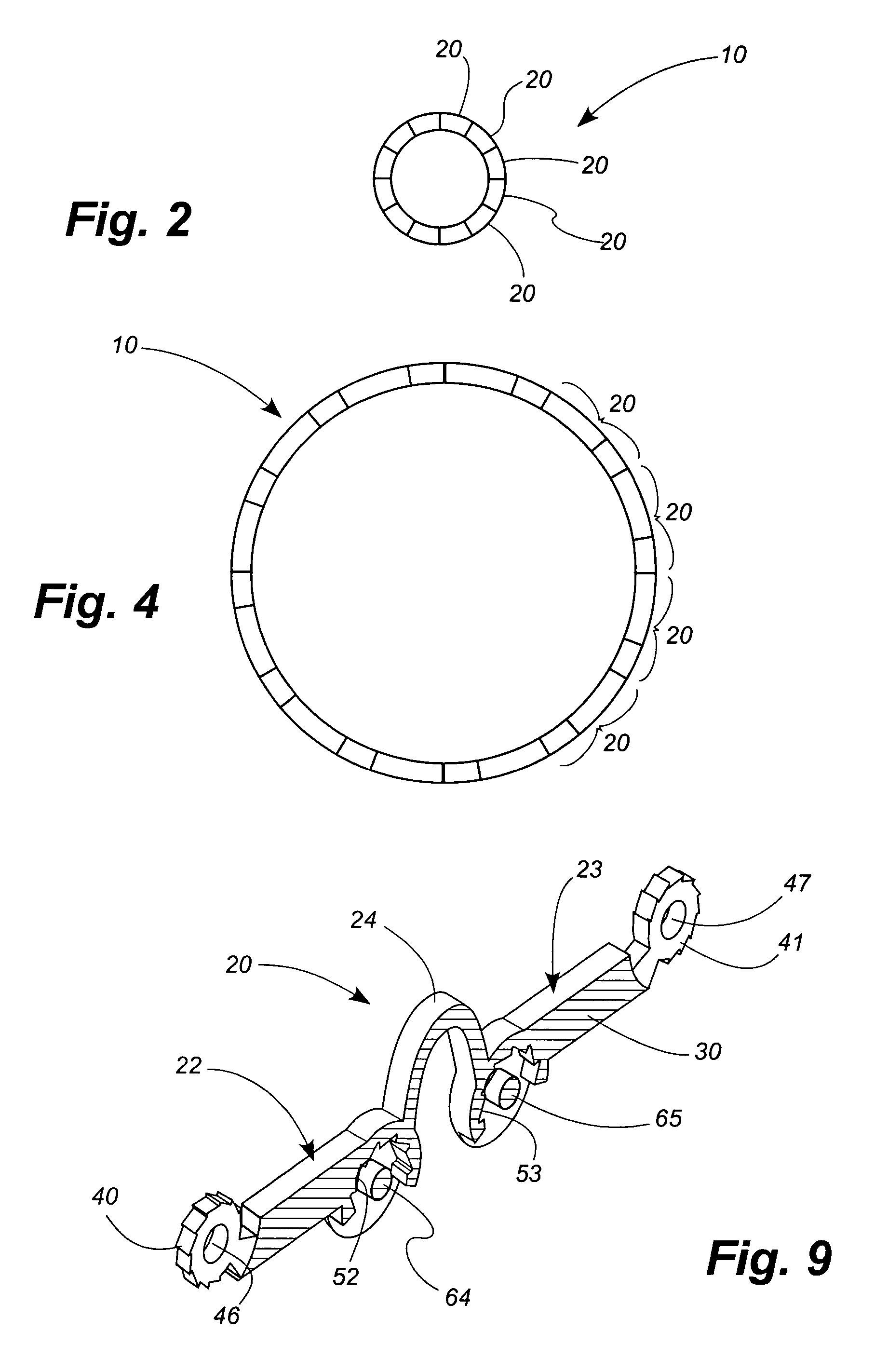
[0081]Referring now to the drawings, in which like numerals indicate like elements throughout the several views, FIGS. 1–4 show a stent 10 according to a disclosed embodiment of the present invention. The stent 10 is comprised of a plurality of links 20. FIGS. 1 and 2 show the stent 10 in its unexpanded configuration, in which the stent has a length of approximately 35 mm and a diameter of approximately 2 mm. FIGS. 3 and 4 show the stent 10 in an expanded configuration, in which the stent has a length of approximately 35 mm and a diameter of approximately 7 mm. Thus the diameter of the stent 10 expands to approximately three-and-a-half times its unexpanded diameter, while the length of the stent remains virtually unchanged.

[0082]It will be understood that the dimensions of the stent 10 are disclosed only by way of example, and that the stent can be manufactured of any size suitable for the body lumen into which the stent is to be installed. As will be apparent, the dimensions of the...


PUM


Abstract

A stent is constructed using interconnected links having micro-mechanical latching mechanisms. The micro-mechanical latching elements allow relative rotational movement of interconnected links in one rotational direction but restrict relative rotational movement of the two links in the opposite direction. The micro-mechanical latch surface features are formed using microelectronic mechanical systems (MEMS) manufacturing methods. The male surface of the latching components contains an array of ridges or protrusions, and the receiving surface contains a matching array of recesses. The array of ridges or protrusions and the corresponding recesses have uniformly dissimilar slopes that result in a substantially greater frictional force in one direction than in the opposite direction. The separation distance between the two surfaces is such that the male latch surface is engaged with the receiving surface recesses in the low stress “locked” state, preventing motion in the undesired direction. Each male ridge or protrusion can be underlined by a void that promotes elastic deflection when sliding in the desired direction and recovery into the ‘locked’ state when aligned with the recesses.

Description

TECHNICAL FIELD[0001]The present invention relates generally to medical devices, more particularly stents. More specifically, the present invention relates to an expandable stent that comprises micro-latching hinge joints that permit the stent to expand and thereafter maintain the stent in its expanded configuration.BACKGROUND OF THE INVENTION[0002]Stents are generally tubular devices used to prop open a segment of blood vessel or other anatomical lumen. They are useful in the treatment of atherosclerotic stenosis in blood vessels, maintaining blood perfusion to downstream tissue after opening of a flow restriction.[0003]Various different types of stent designs have been developed for treating diseases of the blood vessels and other tubular structures inside the body. The currently available stents can be classified into two broad categories: balloon-expandable and self-expanding.[0004]A balloon-expandable stent, as described in U.S. Pat. No. 4,776,337, is crimped down onto a folded...

Claims


Application Information

Patent Timeline
Patent Type & Authority Patents(United States)
IPC IPC(8): A61F2/06F16C11/00A61F2/90
CPCA61F2/844A61F2/91A61F2/915Y10T403/32418A61F2002/91558A61F2002/91591A61F2220/0091A61F2002/91541
Inventor WHITE, JASONSTERN, DAVID
Owner MIRUS LLC
Why Eureka
Try Eureka