
Self-constrained segmented stents and methods for their deployment

a segmented stent and self-expanding technology, applied in the field of stents, can solve the problems of uncontrollable recoil of stents, high bending and torsional stress of stents, and difficulty in stent deployment, so as to achieve optimal stent position, optimal stent position, and relative rotational position of segments

Inactive Publication Date: 2006-03-30
XTENT INC
View PDF99 Cites 400 Cited by
  • Summary
  • Abstract
  • Description
  • Claims
  • Application Information

AI Technical Summary

Benefits of technology

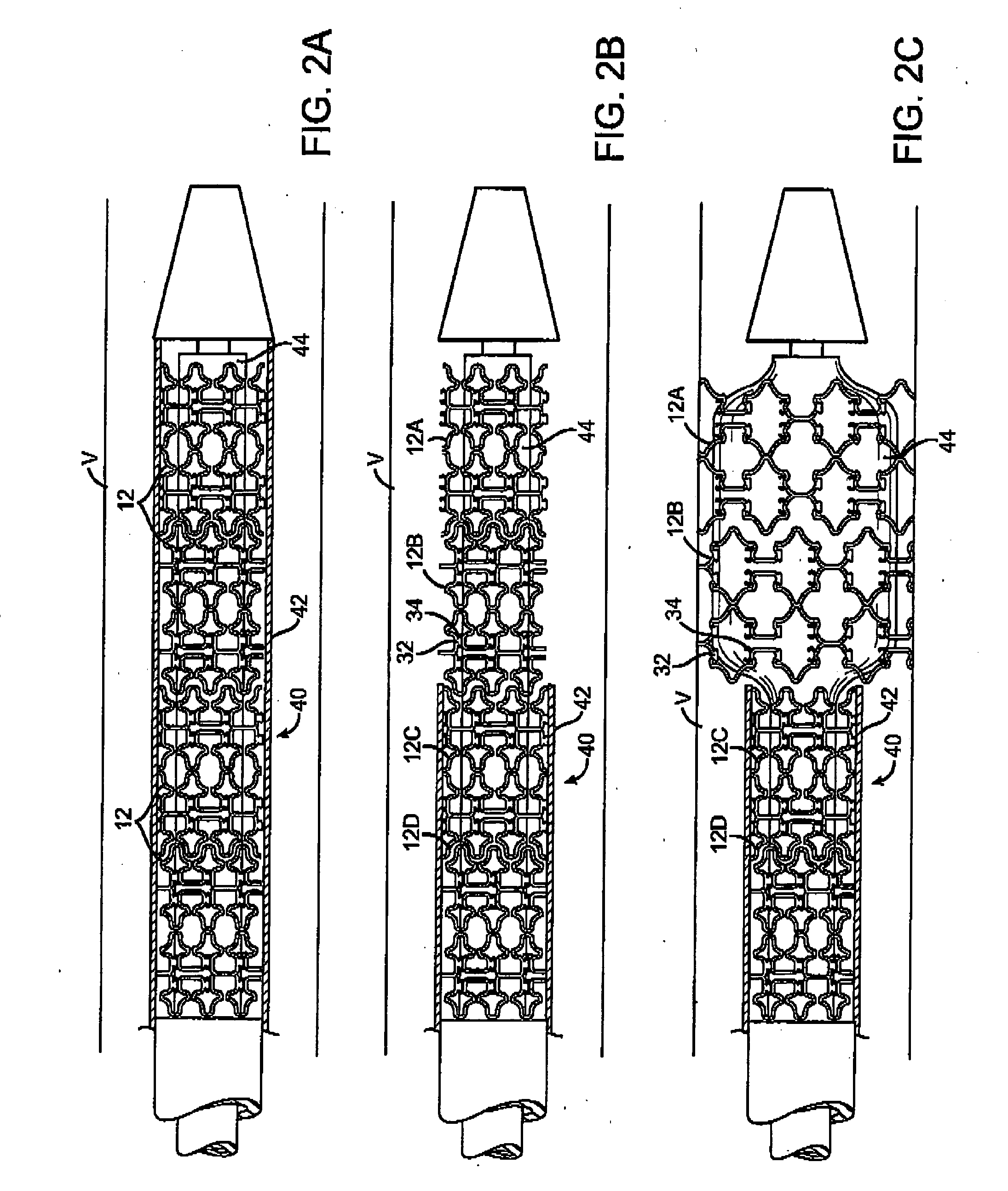
[0010] The invention provides stents, stent delivery systems, and methods of stent delivery that overcome the challenges outlined above and provide other advantages. The stents, delivery systems and methods of the invention are particularly advantageous for the delivery of self-expanding stents, although the principles of the invention may also be applied to balloon-expandable stents. In preferred embodiments, the invention provides segmented stents, and systems and methods for the delivery of such stents, which enable greater control and precision during stent deployment so that optimal stent position, inter-segment spacing, and relative rotational position of segments is achieved.

Problems solved by technology

After deployment, these stents may be subject to very high bending and torsional stresses due to limb movement and patient activity.
Self-expanding stents do, however, present certain challenges.
One such challenge relates to the ability to maintain sufficient control over the stents during deployment to precisely implant them at a desired location.
However, this resiliency also can cause such stents to recoil in an uncontrollable fashion when released, wherein the stents jump distally away from the catheter (known as “watermelon seeding”) and / or rotate about their longitudinal or transverse axes.
This may result in the stent being placed in a sub-optimal location or orientation relative to the desired treatment site.
Such lack of control can be particularly problematic in applications where more precise stent placement is necessary, such as in the delivery of segmented stents.

Method used


Image

  • Self-constrained segmented stents and methods for their deployment
  • Self-constrained segmented stents and methods for their deployment
  • Self-constrained segmented stents and methods for their deployment

Examples


Embodiment Construction

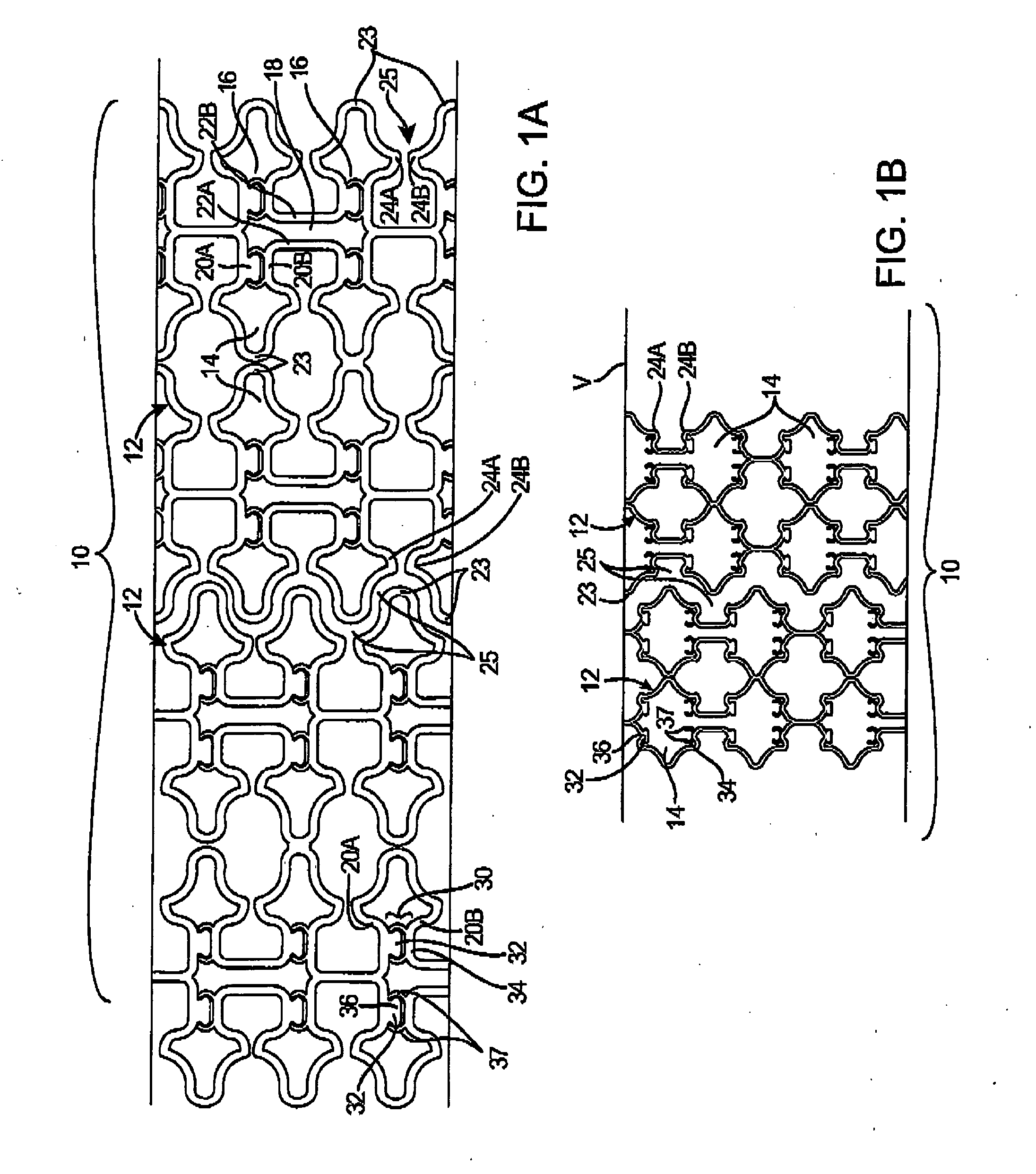
[0042] Reference is now made to FIGS. 1A-B, which show a stent 10 according to the invention in a collapsed configuration for delivery (FIG. 1A), and in an expanded configuration in a body lumen V (FIG. 1B). In this embodiment, a stent 10 comprises a plurality of tubular segments 12 that are laser cut from a metal tube into a desired geometry. While a number of preferred stent constructions are described herein, it should be understood that the principles of the invention are applicable to stents of various geometries, materials, and dimensions. Segments 12 may be formed of wire, ribbon, or mesh, cut or etched from a sheet or tube, or molded or woven from polymer, metal, or textile strands, and may be made of various metals, polymers, ceramics, textiles, proteins, or other biocompatible materials. Stent 10 may consist of up to 20 or more segments 12, each being 2-30 mm in length, having a combined length as long as 200 mm or more. In a preferred embodiment, stent 10 is self-expandin...


PUM


Abstract

A self-expanding stent includes a plurality of segments having a collapsed configuration and an expanded configuration. Preferably, the segments are unconnected to each other in at least the expanded configuration. The segments include restraining structures that temporarily restrain them from expansion until activated. This allows the user to position the desired number of segments at a treatment site and to deploy them simultaneously, thereby avoiding misalignment, overlap, and excessive spacing between segments. In preferred embodiments, multiple segmented stents of user-selectable length may be deployed at multiple locations in a single intervention.

Description

CROSS-REFERENCES TO RELATED APPLICATIONS [0001] NOT APPLICABLESTATEMENT AS TO RIGHTS TO INVENTIONS MADE UNDER FEDERALLY SPONSORED RESEARCH OR DEVELOPMENT [0002] NOT APPLICABLEREFERENCE TO A “SEQUENCE LISTING,” A TABLE, OR A COMPUTER PROGRAM LISTING APPENDIX SUBMITTED ON A COMPACT DISK. [0003] NOT APPLICABLE BACKGROUND OF THE INVENTION [0004] The present invention relates generally to stents for vascular and other applications, and more specifically to self-expanding stents and methods for deploying such stents with greater precision and control. [0005] Stents are tubular prostheses used for scaffolding of arteries and other vessels, fixation of devices such as heart valves and vascular grafts, and other purposes. Stents are generally of two types: balloon expandable or self-expanding. Balloon expandable stents are made of malleable materials and implanted by placing the stent over a tiny balloon at the tip of a catheter, positioning the catheter in a target lumen, and inflating the ...

Claims


Application Information

Patent Timeline
IPC IPC(8): A61F2/06A61F2/82
CPCA61F2/91A61F2/915A61F2/95A61F2002/826A61F2002/828A61F2002/91508A61F2220/0016A61F2002/9155A61F2002/91591A61F2002/9505A61F2220/0025A61F2250/0071A61F2220/0008A61F2002/91533
Inventor ACOSTA, PABLOWELK, CRAIGGRAINGER, JEFFRY J.
Owner XTENT INC
Learn More