Highly flexible heart valve connecting band

a technology of connecting band and heart valve, which is applied in the field of high-flexible prosthetic tissue valves and associated connecting bands or sewing rings, can solve the problems of increasing pressure drop through, and achieve the effect of facilitating supra-annular attachment of prosthetic valves and enhancing flexibility of cusps

Active Publication Date: 2006-10-12
EDWARDS LIFESCIENCES CORP
View PDF48 Cites 396 Cited by
  • Summary
  • Abstract
  • Description
  • Claims
  • Application Information

AI Technical Summary

Benefits of technology

[0013] A method of supra-annular implantation of a flexible aortic prosthetic heart valve is also provided by the present invention. The method includes providing a flexible aortic prosthetic heart valve having a supporting structure to which prosthetic leaflets attach and project radially inward and to which a connecting band attaches and projects generally radially outward. The supporting structure and connecting band each generally circumscribe a tube and has an undulating shape with alternating inflow cusps and outflow commissures. The cusps have large radii of curvatures relative to the commissures. An inflow edge of the valve substantially conforms to an outflow edge thereof and follows the undulating shape such that axial gaps are created between adjacent cusps at the commissures. The gaps have a height of at least about 50% of the overall axial height of the supporting structure, and a continuous outwardly directed sewing ridge facilitates supra-annular attachment of the prosthetic valve. The method includes first removing the native leaflets at their line of attachment, th...

Problems solved by technology

Because of the inherent rigidity in conventional heart valves, the natural dilatation of the annulus i...

Method used


Image

  • Highly flexible heart valve connecting band
  • Highly flexible heart valve connecting band
  • Highly flexible heart valve connecting band

Examples


Embodiment Construction

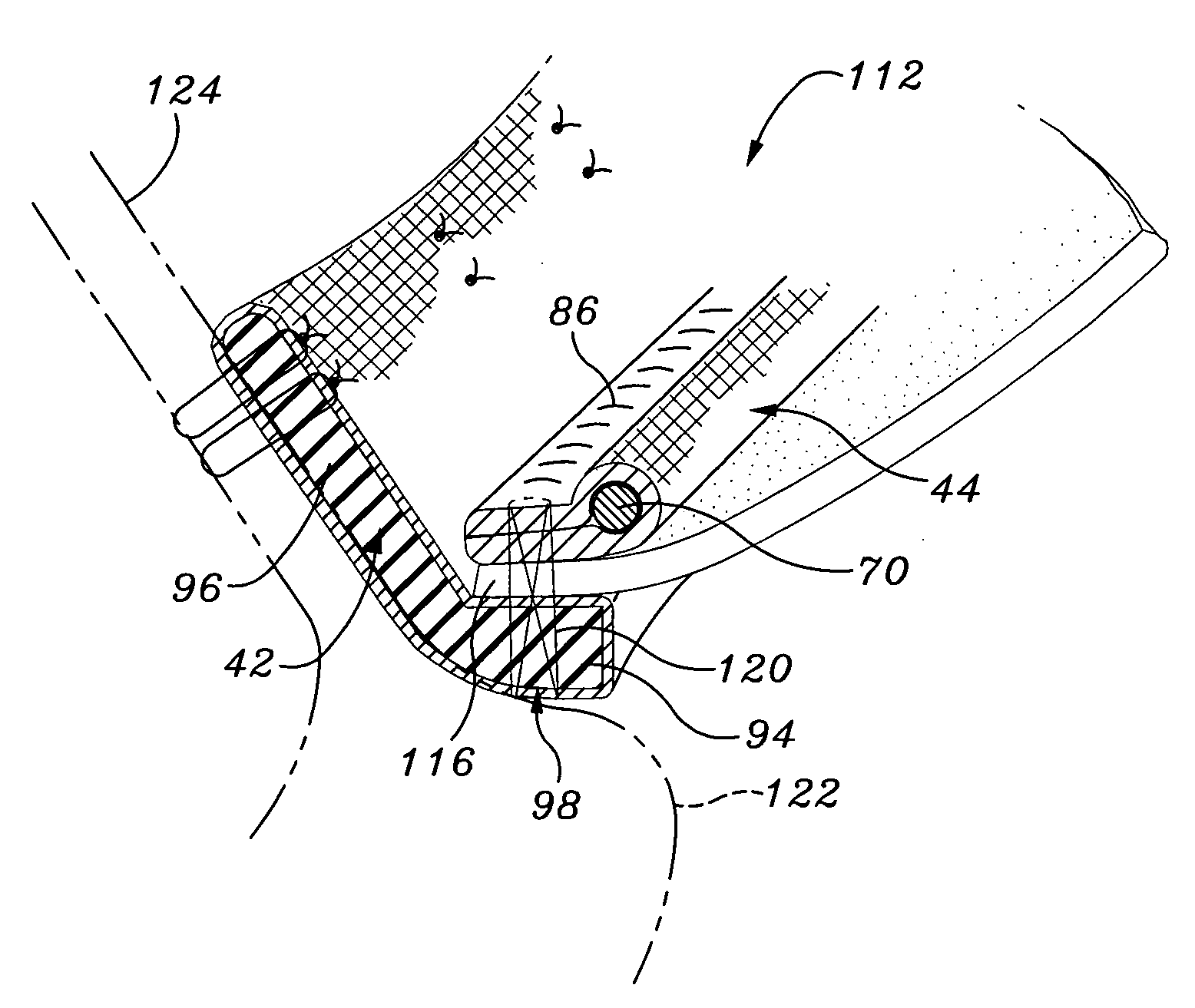
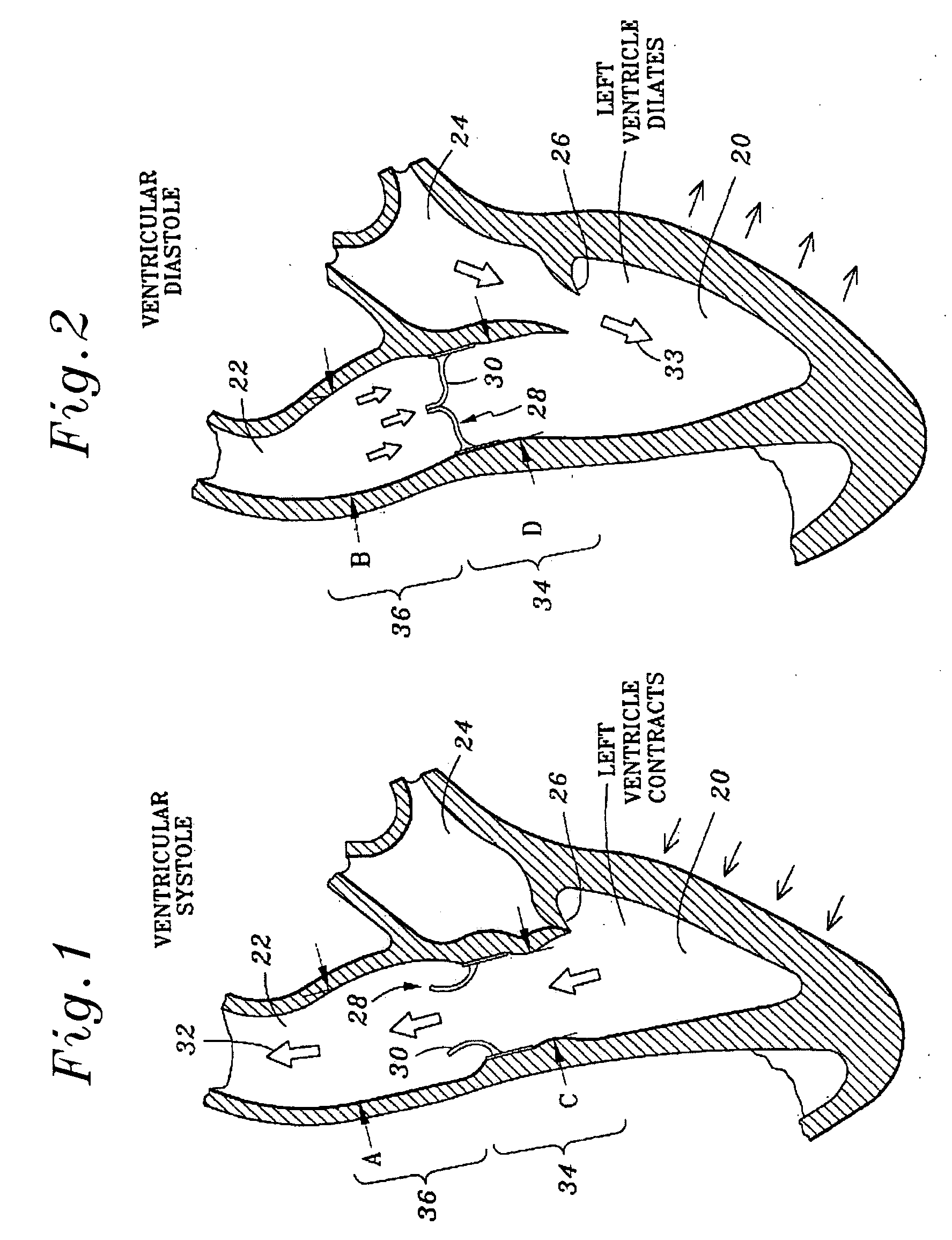
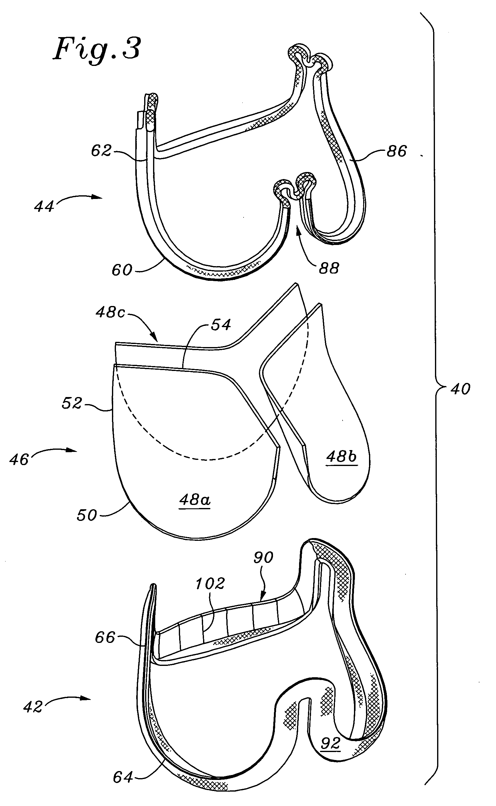
[0036] The present invention provides a sewing ring or connecting band for a highly flexible aortic heart valve that is attached generally along a scalloped or undulating perimeter downstream from where the natural leaflets were originally attached. The natural leaflets include arcuate cusp portions separated by common commissure portions. If the natural valve has three leaflets, and has a vertically oriented flow axis, the leaflets are evenly distributed circumferentially 120° apart with lower (upstream) cusp portions and upper (downstream) generally axially aligned commissure portions. The annular root of the native aortic valve is composed of fibrous tissue and generally conforms to the undulating perimeter of the valve to support the leaflets. In this respect, implanting a prosthetic aortic heart valve of the present invention involves typically excising the natural leaflets and then attaching the prosthetic heart valve proximate the fibrous annulus. Certain embodiments may be a...


PUM


Abstract

A connecting band for a highly flexible tissue-type heart valve having a stent with cusps and commissures that are permitted to move radially. The connecting band follows the cusps and commissures and extends outwardly. The valve is connected to the natural tissue along the undulating connecting band using conventional techniques, such as sutures. The connecting band may be a cloth-covered inner suture-permeable member and attaches to the underside of the valve at the cusps to provide support to the stent and to the outer side of the valve at the commissures. The connecting band includes commissure portions defining generally axial gaps that help permit flexing of the valve. The inner member may include one or more slits along the cusps to enhance flexibility. The inner member may further include a continuous outwardly projecting sewing ridge around its periphery which includes a series of ribs separated by grooves around the inflow edge of the cusps. The sewing ridge enables supra-annular implant of a valve constructed with the connecting band.

Description

FIELD OF THE INVENTION [0001] The present invention relates to prosthetic heart valves, and, more particularly, to a highly flexible prosthetic tissue valve and associated connecting band or sewing ring. BACKGROUND OF THE INVENTION [0002] Prosthetic heart valves are used to replace damaged or diseased heart valves. In vertebrate animals, the heart is a hollow muscular organ having four pumping chambers: the left and right atria and the left and right ventricles, each provided with its own one-way outflow valve. The natural heart valves are identified as the aortic, mitral (or bicuspid), tricuspid and pulmonary valves. The valves of the heart separate chambers therein, and are each mounted in an annulus therebetween. The annuluses comprise dense fibrous rings attached either directly or indirectly to the atrial and ventricular muscle fibers. Prosthetic heart valves can be used to replace any of these naturally occurring valves, although repair or replacement of the aortic or mitral v...

Claims


Application Information

Patent Timeline
IPC IPC(8): A61F2/24
CPCA61F2/2409A61F2/2418A61F2220/0066A61F2220/005A61F2220/0075
Inventor MARQUEZ, SALVADORNGUYEN, DEREKNGUYEN-THIEN-NHON, DIANA
Owner EDWARDS LIFESCIENCES CORP
Why Eureka
Try Eureka