Actively Controllable Stent, Stent Graft, Heart Valve and Method of Controlling Same

a technology of stents and grafts, which is applied in the field of active controllable stents, stent grafts, heart valves, can solve the problems that the existing endograft technology does not allow for the management of this condition, and achieve the effect of improving in situ accommodation

Active Publication Date: 2013-06-27
EDWARDS LIFESCI CARDIAQ
View PDF1 Cites 384 Cited by
  • Summary
  • Abstract
  • Description
  • Claims
  • Application Information

AI Technical Summary

Benefits of technology

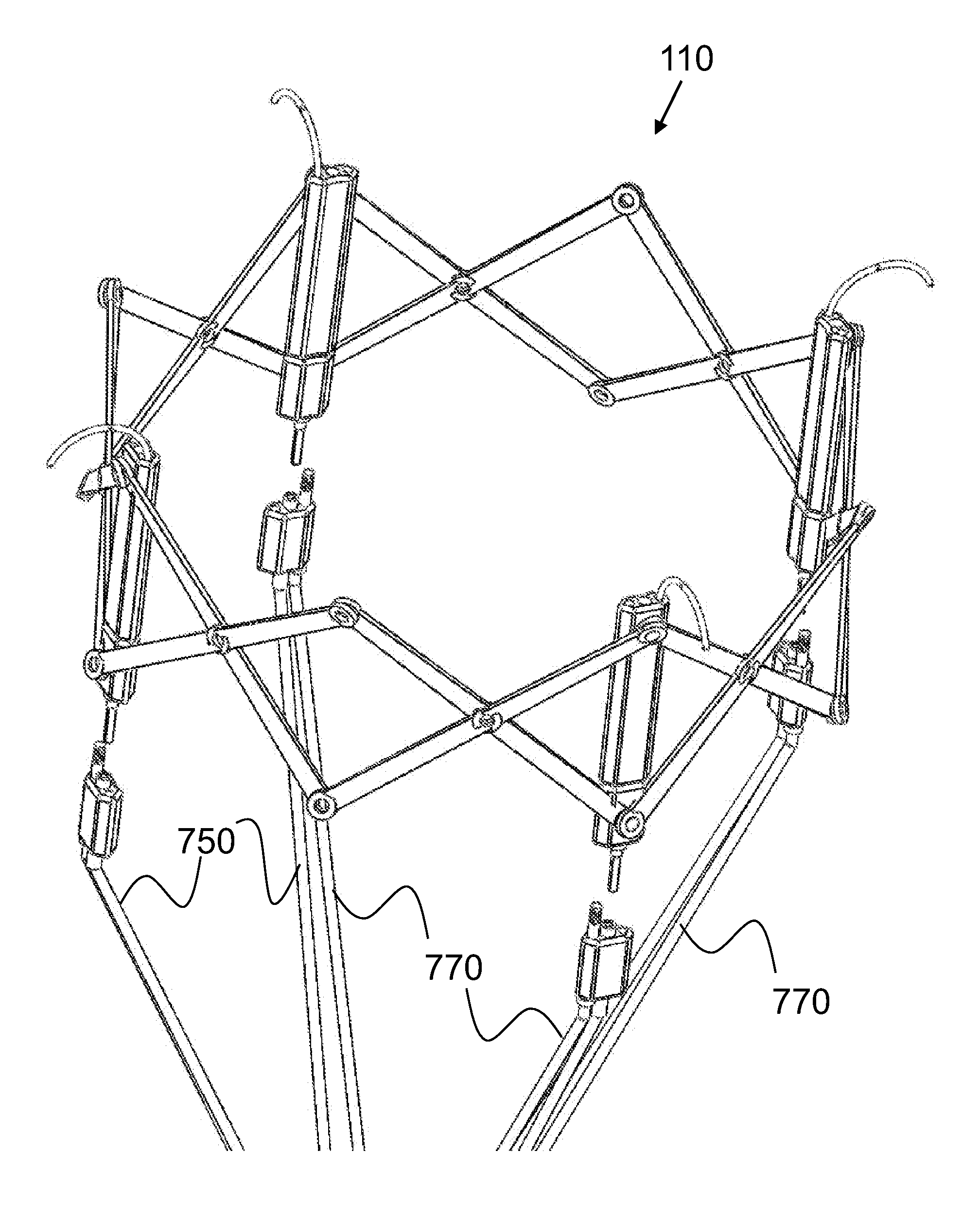
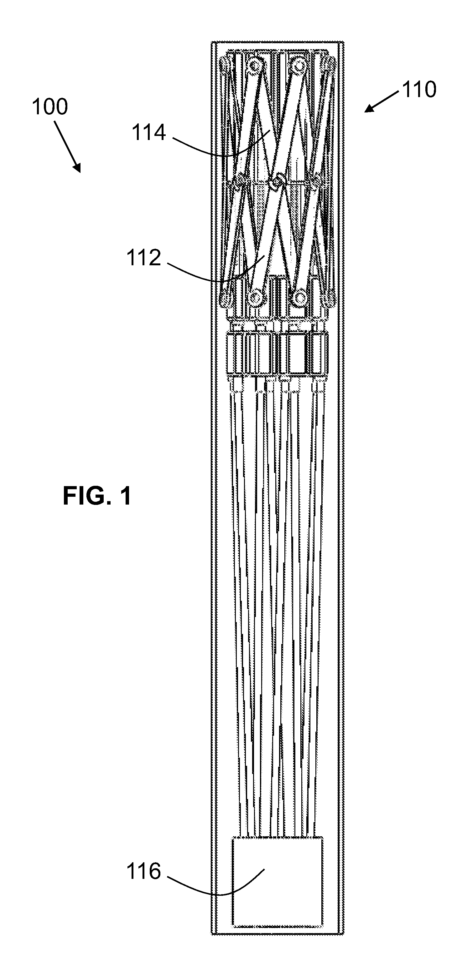
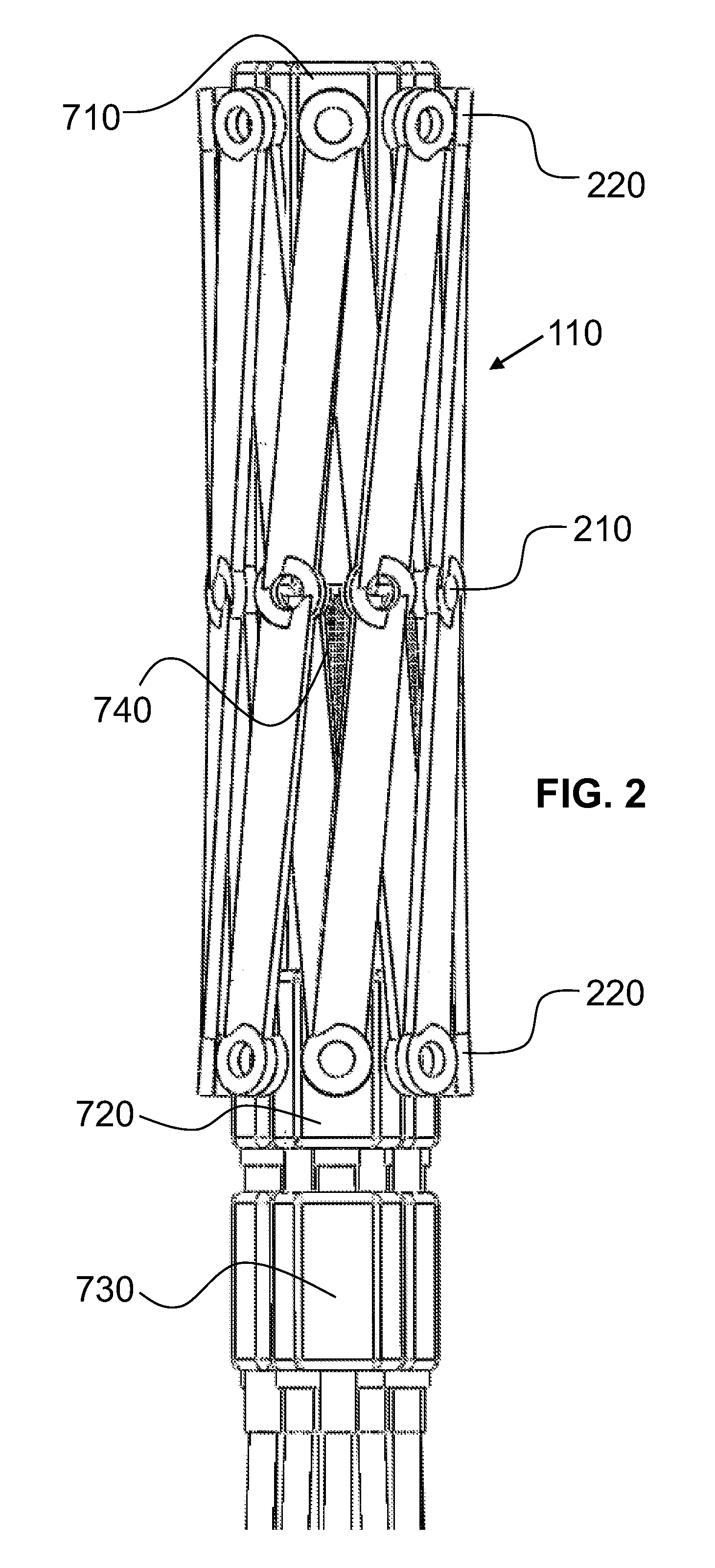
[0023]While some post-implantation remodeling of the aortic neck proximal to an endovascular graft (endograft) has been reported, existing endograft technology does not allow for the management of this condition without placement of an additional endograft sleeve to cover the remodeled segment. Exemplary prostheses of the present invention as described herein allow for better accommodation by the implant of the local anatomy, using an actively controlled expansion device for the sealing interface between the prosthesis collar and the recipient vessel's inner wall. Furthermore, exemplary prostheses of the present invention as disclosed herein are provided with a controllably releasable disconnect mechanism that allows remote removal of an adjustment tool and locking of the retained sealable mechanism after satisfactory positioning and sealing of the endograft. In some exemplary embodiments according to the present invention, the controllably releasable disconnect mechanism may be provided in a manner that allows post-implantation re-docking of an adjustment member to permit post-implantation repositioning and / or resealing of a prostheses subsequent to its initial deployment.

Problems solved by technology

While some post-implantation remodeling of the aortic neck proximal to an endovascular graft (endograft) has been reported, existing endograft technology does not allow for the management of this condition without placement of an additional endograft sleeve to cover the remodeled segment.

Method used


Image

  • Actively Controllable Stent, Stent Graft, Heart Valve and Method of Controlling Same
  • Actively Controllable Stent, Stent Graft, Heart Valve and Method of Controlling Same
  • Actively Controllable Stent, Stent Graft, Heart Valve and Method of Controlling Same

Examples


Embodiment Construction

[0279]As required, detailed embodiments of the present invention are disclosed herein; however, it is to be understood that the disclosed embodiments are merely exemplary of the invention, which can be embodied in various forms. Therefore, specific structural and functional details disclosed herein are not to be interpreted as limiting, but merely as a basis for the claims and as a representative basis for teaching one skilled in the art to variously employ the present invention in virtually any appropriately detailed structure. Further, the terms and phrases used herein are not intended to be limiting; but rather, to provide an understandable description of the invention. While the specification concludes with claims defining the features of the invention that are regarded as novel, it is believed that the invention will be better understood from a consideration of the following description in conjunction with the drawing figures, in which like reference numerals are carried forwar...


PUM


Abstract

Sealable and repositionable implant devices are provided to increase the ability of endovascular grafts and valves to be precisely deployed or re-deployed, with better in situ accommodation to the local anatomy of the targeted recipient anatomic site, and with the ability for post-deployment adjustment to accommodate anatomic changes that might compromise the efficacy of the implant. A surgical implant includes a self-expanding stent of a shape-memory material set to a given shape. The stent has a wall with a portion having a first thickness and a second portion having a thickness greater than the first. The second portion defines a key-hole shaped longitudinal drive orifice. The implant includes a selectively adjustable assembly having adjustable elements and being operable to force a configuration change in at least a portion of the self-expanding stent. The adjustable elements have a part rotatably disposed within the longitudinal drive orifice.

Description

CROSS-REFERENCE TO RELATED APPLICATIONS[0001]This application:[0002]claims the priority, under 35 U.S.C. §119, of copending U.S. Provisional Patent Application No. 61 / 601,961, filed Feb. 22, 2012;[0003]claims the priority, under 35 U.S.C. §119, of copending U.S. Provisional Patent Application No. 61 / 682,558, filed Aug. 13, 2012;[0004]claims the priority, under 35 U.S.C. §119, of copending U.S. Provisional Patent Application No. 61 / 717,037, filed Oct. 22, 2012;[0005]claims the priority, under 35 U.S.C. §119, of copending U.S. Provisional Patent Application No. 61 / 739,711, filed Dec. 19, 2012;[0006]is a continuation-in-part of U.S. patent application Ser. No. 11 / 888,009, filed Jul. 31, 2007, now U.S. Pat. No. 8,252,036, issued Aug. 28, 2012 (which application claims priority to U.S. Provisional Patent Application Nos. 60 / 834,401 and 60 / 834,627, filed Jul. 31, 2006, and Aug. 1, 2006, respectively, and is the parent application to Ser. No. 13 / 544,379 below);[0007]is a continuation-in-pa...

Claims


Application Information

Patent Timeline
Patent Type & Authority Applications(United States)
IPC IPC(8): A61F2/93A61F2/82
CPCA61F2/93A61F2230/0078A61F2/07A61F2/95A61F2002/9511A61F2250/0018A61F2250/0039A61F2250/006A61F2250/0065A61F2/2418A61F2/2439A61F2002/825A61F2220/0091A61F2250/0007A61F2250/001A61F2/89A61F2/90A61F2002/075A61F2002/9534A61F2220/0041A61F2220/0008A61F2220/0016A61F2220/0075A61F2230/0054A61F2/82A61F2/243A61F2/2427
Inventor CARTLEDGE, RICHARDSMITH, KEVIN W.BALES, JR., THOMAS O.DEVILLE, DEREK DEEKLINE, KOREYMENDEZ, MAX PIERREPALMER, MATTHEW A.KIRK, MICHAEL WALTERRIVERA, CARLOSPETERSEN, ERICMCBRAYER, SEAN
Owner EDWARDS LIFESCI CARDIAQ
Why Eureka
Try Eureka