Current measurement

Active Publication Date: 2013-05-23
ANALOG DEVICES INT UNLTD
View PDF14 Cites 116 Cited by
  • Summary
  • Abstract
  • Description
  • Claims
  • Application Information

AI Technical Summary

Benefits of technology

[0067]Calibration may be provided for according to another approach by measuring the current in the live and neutral conductors over a period of time during normal operation, storing the measurements and subsequently using the stored measurements to effect calibration. Therefore the current measurement apparatus may be configured: to operate the first and second measurement devices to measure current in the live and neutral conductors; to store the measured currents; and to adjust subsequent current measurements in dependence on the stored measured currents. Current measurement for calibration purposes may preferably be carried out to reflect normal operation of an electrical circuit comprising the live and neutral conductors, e.g. such that measurement of fluctuations in current caused by noise, switching transients and the like are reduced. The current measurement apparatus may therefore be operative to make plural current measurements over a period of time, such as over a period of minutes or hours, and to determine a current measurement value for storage in dependence on the plural current measurements, e.g. an average value for the plural current measurements.
[0068]The current measurement apparatus may be configured to determine a matching function which is operative to bring a response of the first measurement device and a response of the second measurement device into proximity with each other. Bringing the responses into proximity with each other may provide for improved accuracy of current difference determination, e.g. by reducing an offset between outputs from the two measurement devices. More specifically the matching function may be operative to bring a transfer function of the first measurement device and a transfer function of the second measurement device into proximity with each other. Bringing the transfer functions into proximity with each other may provide for improved accuracy of current difference determination, e.g. by changing at least one of the transfer functions so as to bring the transfer functions into proximity with each other. The current measurement apparatus may be configured to apply, e.g. by way of the calibration source, plural different current values to the f

Problems solved by technology

The current shunt is, however, invasive and provides no isolation.
In addition the current transformer is liable to non-linearity and phase error problems.
In an open loop configuration the Hall current probe is, however, liable to non-linearity and temperature drift.
Ground fault conditions can present a risk of electric shock in electrical systems.
Ground fault electric shock conditions can arise where there is insufficient grounding within an electrical system.
For example the casing of electrical equipment may be improperly grounded such that when a person touches the casing he presents a lower impedance path to ground should the casing become live.
Ground fault electric shock conditions can also arise in electrical systems which meet accepted grounding practice.
Under certain circumstances the TT approach can, however, present problems.
No amount of grounding precautions will prevent electric shock in such circumstances.
An arc fault is another form of circuit condition that is liable to cause damage and be prejudicial to safety.
An arc fault can generate high temperatures and thereby ignite combustible material.
Such a discontinuity is caused by, for example, a broken conductor, a loose terminal or a poor electrical connection at a wire nut.
The parallel arc fault involves arcing between two conductors, such as between a live conductor and a neutral or grounded conductor, and typically arises when conductor insulation is damaged or deteriorates over time

Method used


Image

  • Current measurement
  • Current measurement
  • Current measurement

Examples


first embodiment

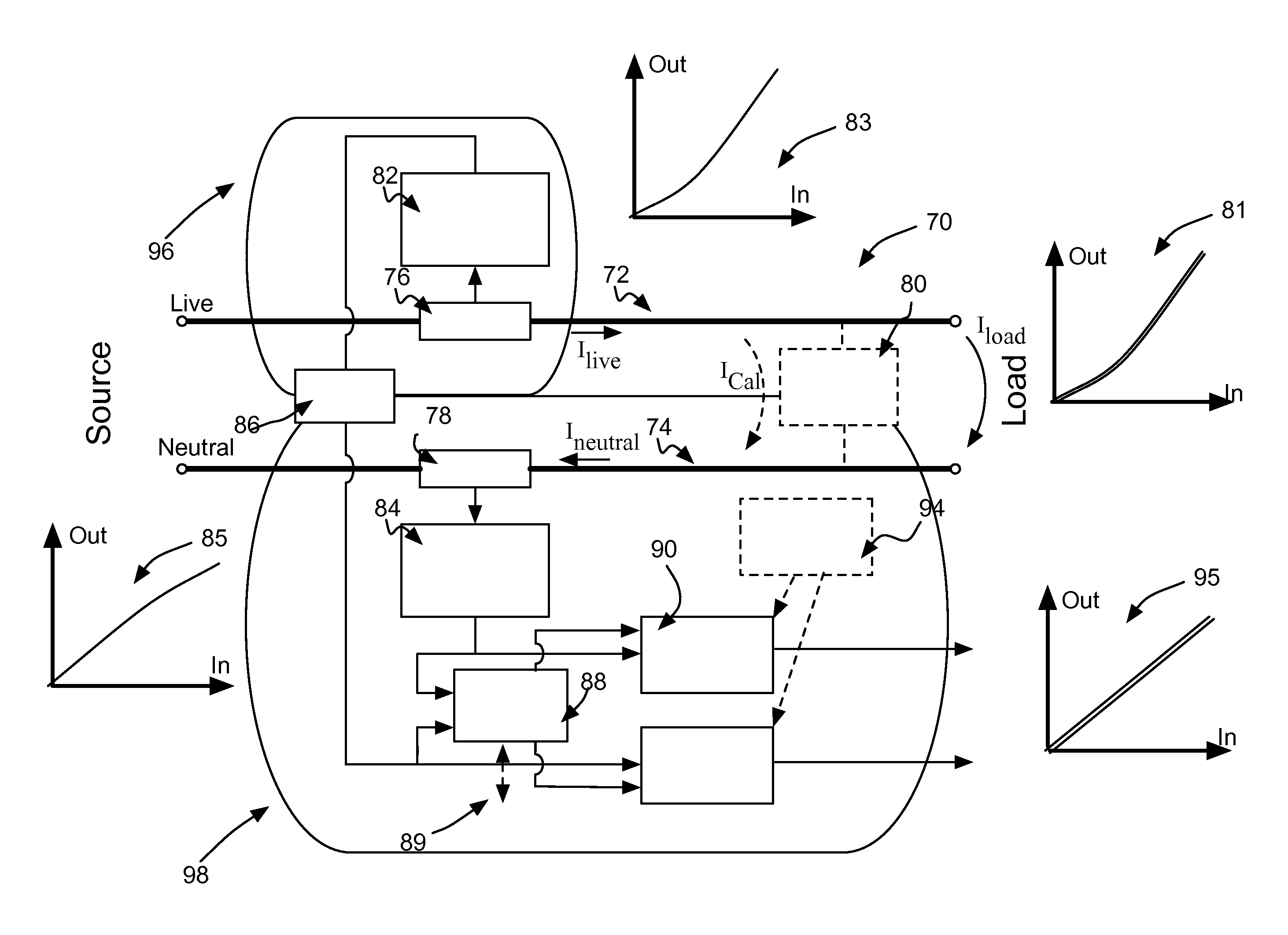
[0116]A block diagram representation of current measurement apparatus 70 according to the invention is shown in FIG. 3. The current measurement apparatus 70 comprises a live conductor 72 and a neutral conductor 74, which convey electrical power from a source to a load in a mains electricity circuit. The current measurement apparatus is installed, e.g. in a distribution box, in residential or business premises. A first shunt resistor 76 (which constitutes a first measurement device) is present in series in the live conductor 72 and a second shunt resistor 78 (which constitutes a second measurement device) is present in series in the neutral conductor 74. The current measurement apparatus 70 further comprises a calibration source 80, which is electrically coupled to the live and neutral conductors 72, 74. As is described further below the calibration source 80 is operative to apply a calibration signal to the live and neutral conductors to calibrate the first and second shunt resistor...

second embodiment

[0127]Current measurement apparatus 100 is shown in FIG. 4. Components in common with the embodiment of FIG. 3 are designated by like reference numerals and the reader's attention is directed to the description provided above with reference to FIG. 3 for a description of such common components. Components particular to the embodiment of FIG. 4 will now be described. The calibration source 80 comprises a calibration resistor 102 in series with a switch 104 with the series arrangement of calibration resistor 102 switch 104 being electrically connected between the live and neutral conductors 72, 74. The current measurement apparatus 100 of FIG. 4 further comprises a calibration control unit 106, which forms part of the signal processing circuitry described above. The calibration control unit 106 is operative to turn the switch 104 on and off in a predetermined fashion with current passing between the live and neutral conductors when the switch 104 is closed. Turning the switch on and ...

third embodiment

[0128]Current measurement apparatus 110 is shown in FIG. 5. Components in common with the embodiments of FIGS. 3 and 4 are designated by like reference numerals and the reader's attention is directed to the description provided above with reference to FIGS. 3 and 4 for a description of such common components. Components particular to the embodiment of FIG. 5 will now be described. Instead of the first shunt resistor 76 of FIGS. 3 and 4 the embodiment of FIG. 5 comprises a current transformer 112 which is configured as described elsewhere herein such that it is operative to measure current flowing in the live conductor 72. Although not shown in FIG. 5 the current transformer comprises a burden resistor connected across the coil of the transformer and which is operative in accordance with normal design practice. In view of the inherently isolating characteristic of the current transformer 112 there is no need to provide for isolation between the processing chains of the current trans...


PUM


Abstract

The present invention relates to current measurement apparatus. The current measurement apparatus comprises first and second measurement devices with each of the first and second measurement devices being operative to measure current in a respective one of a live conductor and a neutral conductor substantially simultaneously. The current measurement apparatus is operative to make plural different determinations in dependence on the substantially simultaneous current measurements.

Description

FIELD OF THE INVENTION[0001]The present invention relates to current measurement apparatus configured in particular but not exclusively for measurement of current flowing in mains electrical circuits and a current measurement method using such current measurement apparatus.BACKGROUND TO THE INVENTION[0002]Accurate measurement of current is required for different applications in the electricity consumption and generation fields. For example accurate current measurement is required for metering of electricity usage or generation, for over current protection and for sub-metering, e.g. in a building in which there are distinct electricity consumers for whom metering is required on an individual basis.[0003]A current shunt provides one approach to measuring the high values of current encountered in such applications. In use a shunt of known resistance is provided in series with a load and the voltage developed across the shunt by the load drawn current is measured. The current passing th...

Claims


Application Information

Patent Timeline
IPC IPC(8): G01R31/02H02H3/32G01R35/00G01R19/00G01R23/02
CPCG01R19/00G01R23/02G01R31/025G01R21/06H02H3/32H02H3/006G01R35/005G01R19/16547G01R31/52H02H1/0015G01R19/2506H02H1/003
Inventor DANESH, SEYED AMIR ALIHURWITZ, JONATHAN EPHRAIM DAVID
Owner ANALOG DEVICES INT UNLTD
Why Eureka
Try Eureka