Charge pump circuit and operation control method thereof

a pump circuit and pump technology, applied in process and machine control, instruments, apparatus without intermediate ac conversion, etc., can solve the problems of unstable output voltage, small input voltage cannot be produced, and arbitrary output voltage other than an integral multiple of input voltage cannot be obtained, so as to reduce output voltage fluctuations

Inactive Publication Date: 2012-05-10
RICOH KK
View PDF3 Cites 24 Cited by
  • Summary
  • Abstract
  • Description
  • Claims
  • Application Information

AI Technical Summary

Benefits of technology

[0008]An object of the present invention to solve the above-described problem is to provide a charge pump circuit which is capable of obtaining an output voltage which is smaller than an input voltage and an output voltage which is greater than the input voltage with one flying capacitor at the same time, and is capable of performing settings of both the above output voltages and reducing output voltage fluctuations due to load fluctuations, and an operation control method thereof.

Problems solved by technology

However, in the first conventional example, an output voltage becomes a voltage which is N times an input voltage, and a voltage which is smaller than the input voltage can not be produced.
And additionally, an arbitrary output voltage other than an integral multiple of the input voltage can not be obtained, either.
Moreover, in the first conventional example, when an input voltage fluctuates, an output voltage also fluctuates, and no countermeasures are taken for load fluctuations, and therefore an output voltage is unstable.
Additionally, as well as the first conventional example, in the second conventional example, an arbitrary output voltage can not be obtained, and an output voltage is also unstable in terms of input voltage fluctuations and load fluctuations.
However, in the third conventional example, it is not possible to change the on-duty cycle of the switch section for each individual output voltage, and therefore an output voltage which can be controlled is limited to one.
Moreover, in the third conventional example, a countermeasure for load fluctuations is not taken, and therefore there is a problem in that an output voltage is unstable.
Furthermore, an inductor is needed, and therefore it is difficult to achieve a circuit integration.

Method used


Image

  • Charge pump circuit and operation control method thereof
  • Charge pump circuit and operation control method thereof
  • Charge pump circuit and operation control method thereof

Examples


embodiment

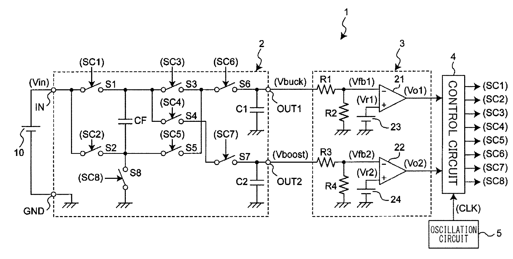
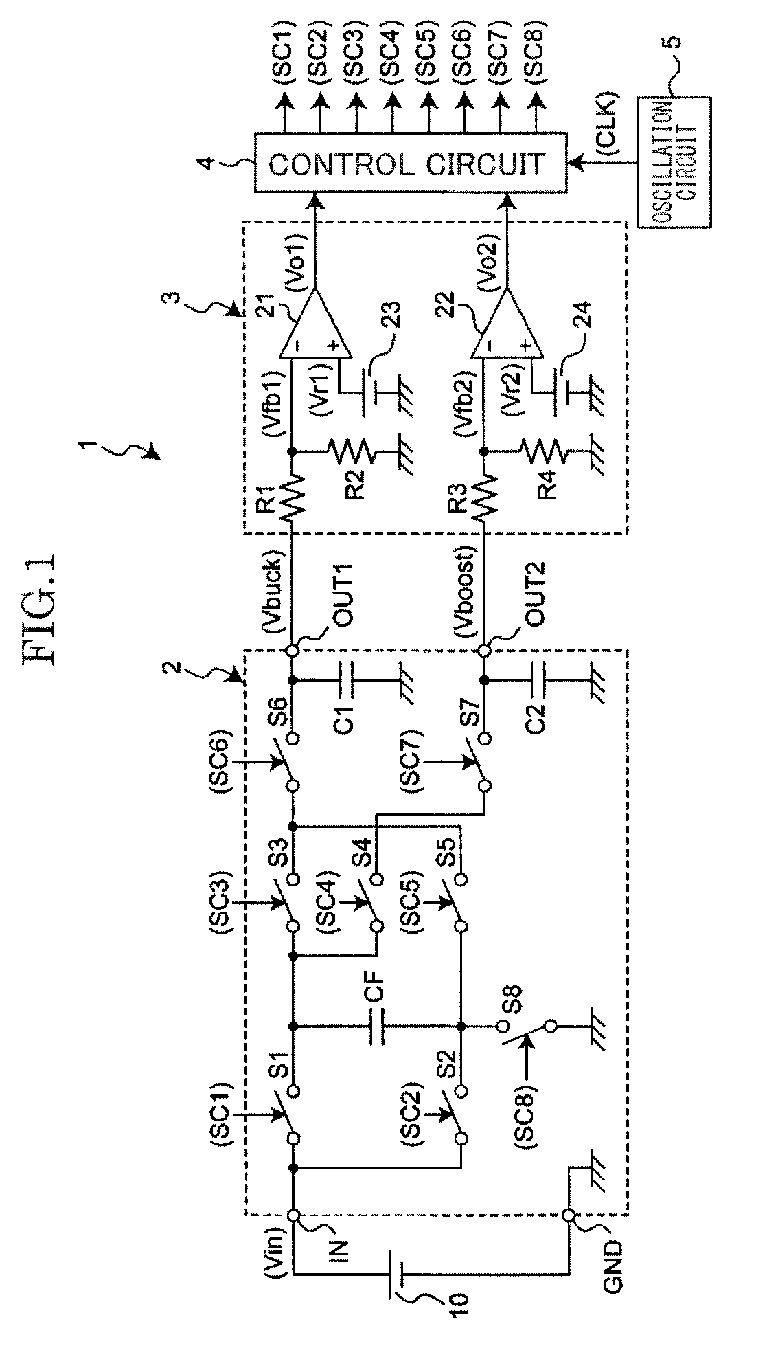
[0039]FIG. 1 is a diagram illustrating a circuit example of a charge pump circuit of an embodiment of the present invention.

[0040]A charge pump circuit 1 in FIG. 1 steps down an input voltage Vin which is inputted to an input terminal IN from a battery or a DC (direct current) power supply 10 such as a constant voltage circuit and so on, and produces and outputs a step-down output voltage Vbuck from a step-down output terminal OUT1, and steps up the input voltage Vin and produces and outputs a step-up output voltage Vboost from a step-up output terminal OUT2.

[0041]The charge pump circuit 1 includes a voltage conversion circuit 2, an output voltage detection circuit 3, a control circuit 4, and an oscillation circuit 5. The voltage conversion circuit 2 produces a step-down output voltage Vbuck and a step-up output voltage Vboost each from an input voltage Vin, and outputs the step-down output voltage Vbuck from a step-down output terminal OUT1 and outputs the step-up output voltage Vb...


PUM


Abstract

A charge pump circuit which steps down an input voltage inputted from an input terminal and outputs it as a step-down output voltage from a step-down output terminal, and steps up the input voltage and outputs it as a step-up output voltage from a step-up output terminal, includes: a voltage conversion circuit having a flying capacitor, a step-down output capacitor, a step-up output capacitor, and a plurality of switches, wherein the flying capacitor, the step-down output capacitor, the step-up output capacitor, and the switches are connected, and the voltage conversion circuit is capable of switching connection states by switching each on / off state of the switches; an output voltage detection circuit unit which makes a comparison of a voltage between the step-down output voltage and a first predetermined voltage, and makes a comparison of a voltage between the step-up output voltage and a second predetermined voltage, and produces and outputs each signal indicating each result of the comparisons; and a control circuit unit which performs a switching control depending on each signal outputted from the output voltage detection circuit unit.

Description

TECHNICAL FIELD[0001]The present invention relates to a charge pump circuit which produces and outputs a plurality of different voltages, and in particular, a charge pump circuit which respectively produces and outputs a step-down voltage which is smaller than an input voltage and a step-up voltage which is greater than an input voltage, and an operation control method thereof.BACKGROUND ART[0002]In a first conventional example of a charge pump circuit, a flying capacitor is charged with an input voltage, and an output capacitor which is connected to an output terminal is charged with a voltage in which the input voltage is added to the charged voltage in the flying capacitor, and thereby a voltage which is twice the input voltage is produced (see Japanese patent publication number S56-12859). In the case of producing a greater voltage, a voltage of the flying capacitor which is charged with the input voltage is further added to a voltage of the output terminal which is charged to t...

Claims


Application Information

Patent Timeline
Patent Type & Authority Applications(United States)
IPC IPC(8): G05F1/10
CPCH02M3/07
Inventor NISHIDA, JUNJI
Owner RICOH KK
Why Eureka
Try Eureka