Method for producing optical film, optical film, polarizing plate and display

a technology of optical film and polarizing plate, which is applied in the direction of instruments, polarising elements, other domestic objects, etc., can solve the problems of not being able to conduct substantial facility modification, and not being able to smoothly peel the film from the metal support. , to achieve the effect of reducing the limitations of film manufacturing conditions, enhancing productivity, and eliminating the poor peeling region of the metal suppor

Inactive Publication Date: 2010-04-29
KONICA MINOLTA OPTO
View PDF2 Cites 25 Cited by
  • Summary
  • Abstract
  • Description
  • Claims
  • Application Information

AI Technical Summary

Benefits of technology

[0037]According to the present invention, in the manufacturing method of optical films via the solution casting film forming method, by casting a dope onto the surface of a metal support, it is possible to eliminate the poor peeling regions of the metal support by casting the dope onto the surface of the metal support after forming a surface treatment film by applying an atmospheric pressure plasma treatment or an excimer UV treatment onto the surface of the metal support. By doing so, limitations of film manufacturing conditions are reduced to enhance productivity. Further, by enhan

Problems solved by technology

In such region, it is not possible to smoothly peel the film from the metal support, whereby fairly pronounced fluttering and peeling noise are accompanied.
In such a case, problems have occurred in which it is necessary to conduct substantial facility modification such as extension of the post-drying process to enhance the capacity of solvent recovery facilities and to lower the residual solvent amount to the limit.
As a result, when the drying period

Method used


Image

  • Method for producing optical film, optical film, polarizing plate and display
  • Method for producing optical film, optical film, polarizing plate and display
  • Method for producing optical film, optical film, polarizing plate and display

Examples


example 1

Atmospheric Pressure Plasma Treatment

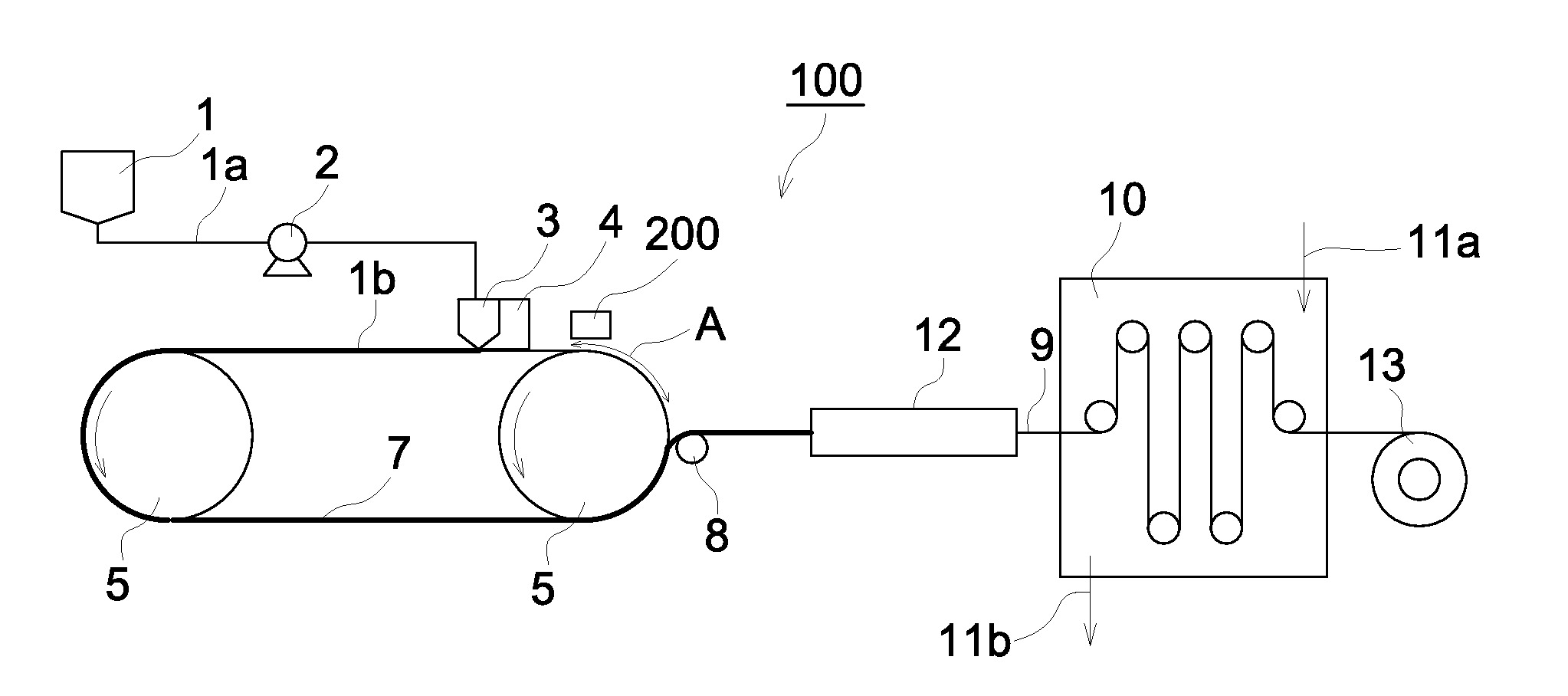
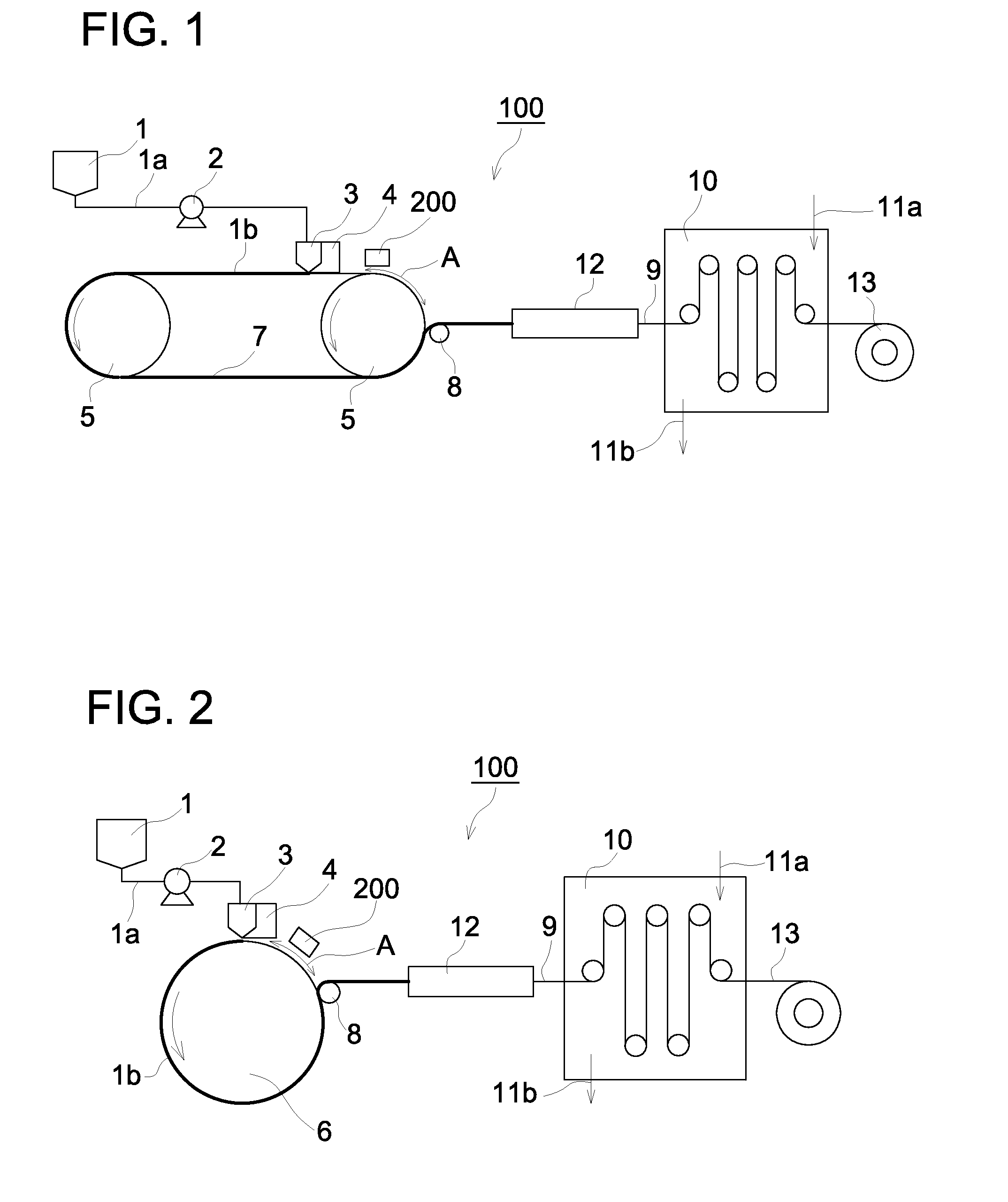
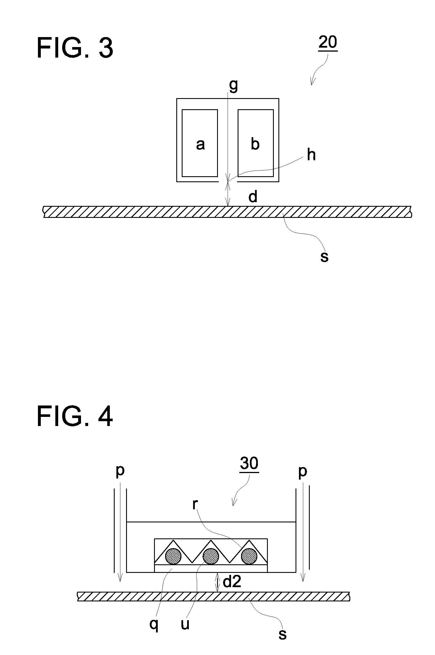
[0279]In the condition in which gap (d) between blowing slit (h) and the surface of metal support (s) of atmospheric pressure plasma apparatus (20) was regulated to 2 mm, while conveying metal support (s) below plasma apparatus (20), 0.0005-second plasma exposure treatment was carried out. Since it was difficult to determine such accurate contact time of radicals with metal support (s), plasma exposure time, as described herein, refers to the moving time of a certain point on the surface of metal support (s) when the certain point moves the length corresponding to the aperture width of blowing slit (h) under blowing slot (h). When, for example, the aperture width of blowing slit (h) is 2 mm and the moving rate of metal support (s) is 2 mm / second, the plasma exposure time results in 1 second. Further, the used volume of reactive gas (g) was regulated to 3 m3 / minute per meter of the exposure width. At that time, reactive gas (g) employed for atmosp...

example 2

[0280]Example 2 was carried out in the same manner as Example 1, except that the plasma exposure treating time was changed to 0.01 second, while the concentration of methylene chloride and methanol near the surface of metal support (s) prior to entrance to atmospheric pressure plasma apparatus (2) was changed to 6,500 ppm and 1,500 ppm, respectively.

example 3

[0281]Example 3 was carried out in the same manner as Example 2, except that oxygen of 1% by volume was added to reactive gas (g).


PUM

PropertyMeasurementUnit
Timeaaaaaaaaaa
Wavelengthaaaaaaaaaa
Force constantaaaaaaaaaa

Abstract

A method of manufacturing an optical film by a solution casting method, in which a poor peeling region of a metal support can be eliminated by casting a dope on the surface of the metal support after a surface treatment film is formed on the surface of the metal support by atmospheric pressure plasma treatment or excimer UV treatment. Consequently, limitation on the conditions of film production is reduced and productivity is enhanced. Furthermore, since peeling of the film is enhanced, lateral variation in peeling position is reduced and variation in retardation value is reduced sharply, and thereby an optical film having optical characteristics excellent in transparency and flatness can be manufactured. Consequently, a method for manufacturing an optical film, an optical film, a polarizing plate and a display device which meet the demands of a high quality thin and wide protective film for polarizing plate can be provided.

Description

TECHNICAL FIELD[0001]The present invention relates to a manufacturing method of an optical film which is applicable to various functional films such as a polarizing plate protective film, a retardation film or a viewing angle enlarging film, employed in a liquid crystal display device (LCD), or an antireflection film employed in a plasma display, as well as relates to an optical film, a polarizing plate, and a display device.BACKGROUND[0002]In recent years, liquid crystal display devices have been employed in television sets and oversized monitors due to enhancement of their image quality and high resolution technologies. Specifically, demand for the size increase of these liquid crystal devices and cost reduction via efficient production have increased for materials of liquid crystal displays, and an increase in width of optical films have been desired.[0003]Further, in recent years, to correspond to the rapid increase in liquid crystal TVs, demand for optical films is rapidly incr...

Claims


Application Information

Patent Timeline
IPC IPC(8): C08L1/10B29D7/01G02B5/30
CPCB29C41/28B29K2001/00G02F1/133528B29K2995/0018G02B5/3033B29K2001/12B29C41/24B29C41/34B29L2011/00G02B5/30
Inventor KANEKO, TADAHIRO
Owner KONICA MINOLTA OPTO
Why Eureka
Try Eureka