Power converting device and method for controlling the same

Active Publication Date: 2009-07-02
HITACHI IND PROD LTD
View PDF3 Cites 28 Cited by
  • Summary
  • Abstract
  • Description
  • Claims
  • Application Information

AI Technical Summary

Benefits of technology

[0007]By obtaining the amplitude of the positive phase active fundamental current from the Fourier series, the current instruction value can be generated by, for example, removing the positive ph

Problems solved by technology

Therefore, the effect of the compensation is weak for harmonic components fluctuating in low frequencies, etc.
Consequently, the effect of c

Method used


Image

  • Power converting device and method for controlling the same
  • Power converting device and method for controlling the same
  • Power converting device and method for controlling the same

Examples


Example

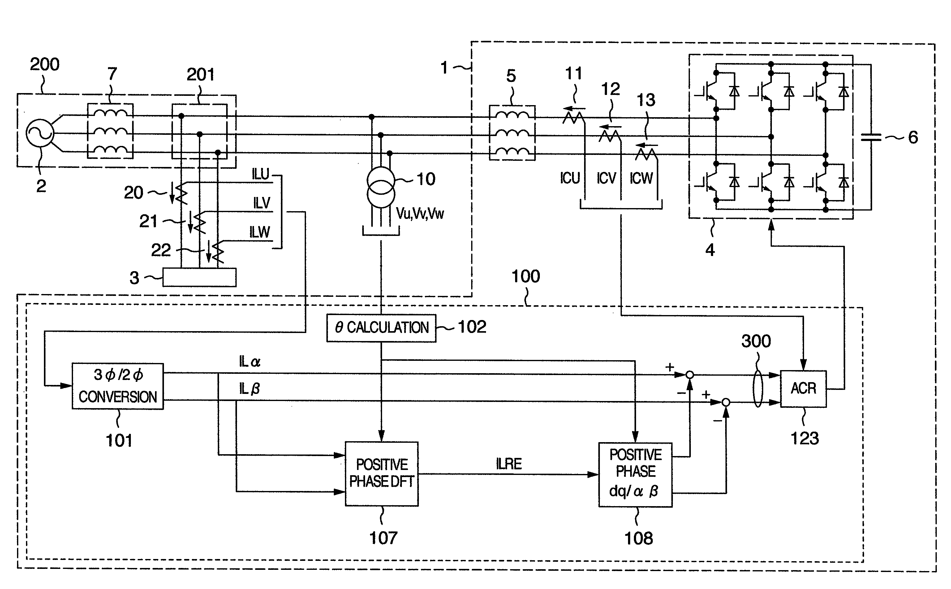
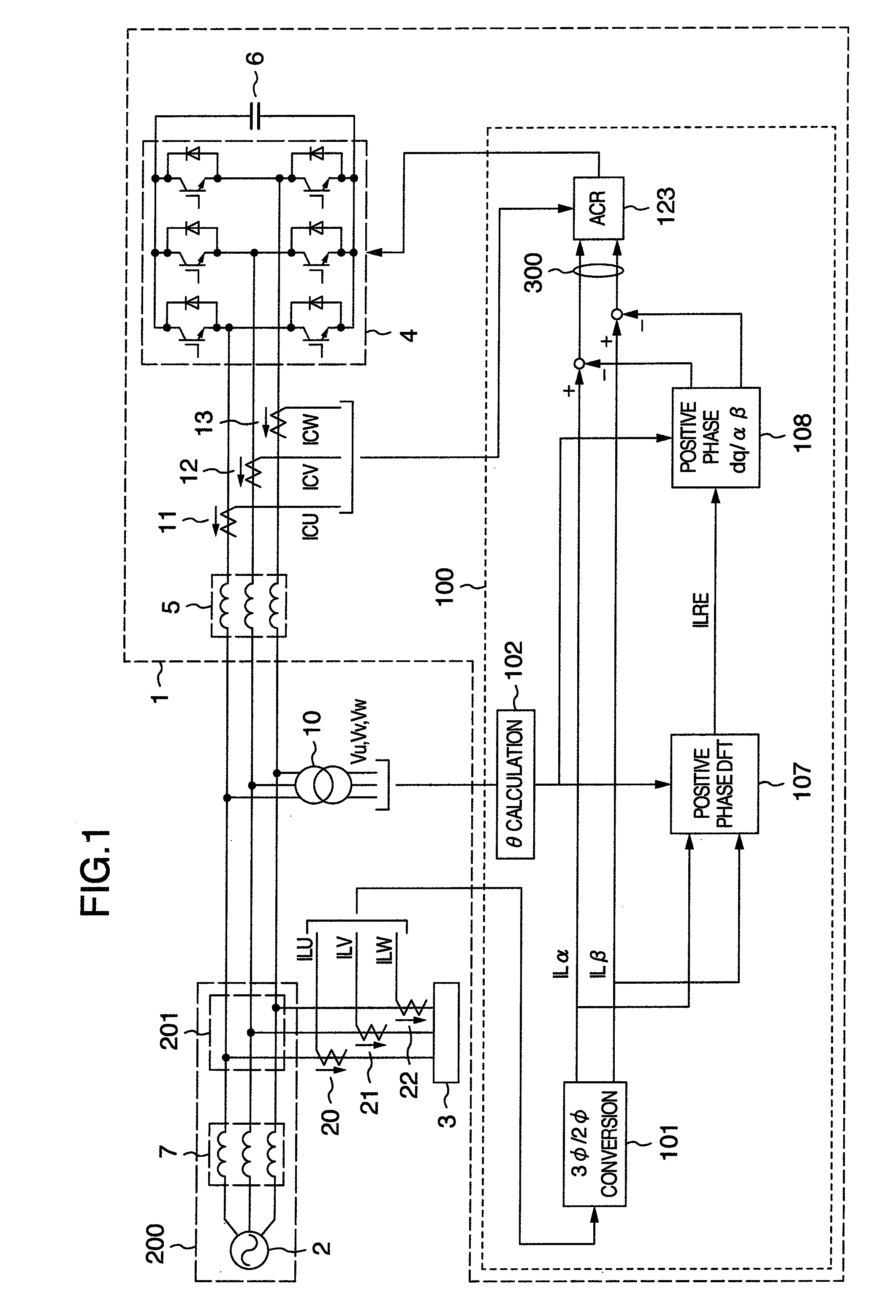
[0017]A first embodiment in accordance with the present invention will be described referring to FIG. 1.

[0018]As shown in FIG. 1, a power converting device 1 in accordance with the first embodiment is connected to a load 3 and an AC system 200 of a commercial power system at a connecting point 201. In FIG. 1, the AC system 200 is represented by an AC power supply 2 and a system impedance 7. The system impedance 7 means power line impedance and transformer impedance. When the load current fluctuates, the voltage drop occurring in the system impedance 7 also fluctuates, by which voltage fluctuation occurs at the connecting point 201 of the load 3 and the AC system 200. The power converting device 1 of this embodiment reduces and suppresses the voltage fluctuation at the connecting point and the system current fluctuation which are caused by the load current fluctuation.

[0019]The power converting device 1 of this embodiment includes a main circuit unit and a control calculation unit 10...

Example

Embodiment 2

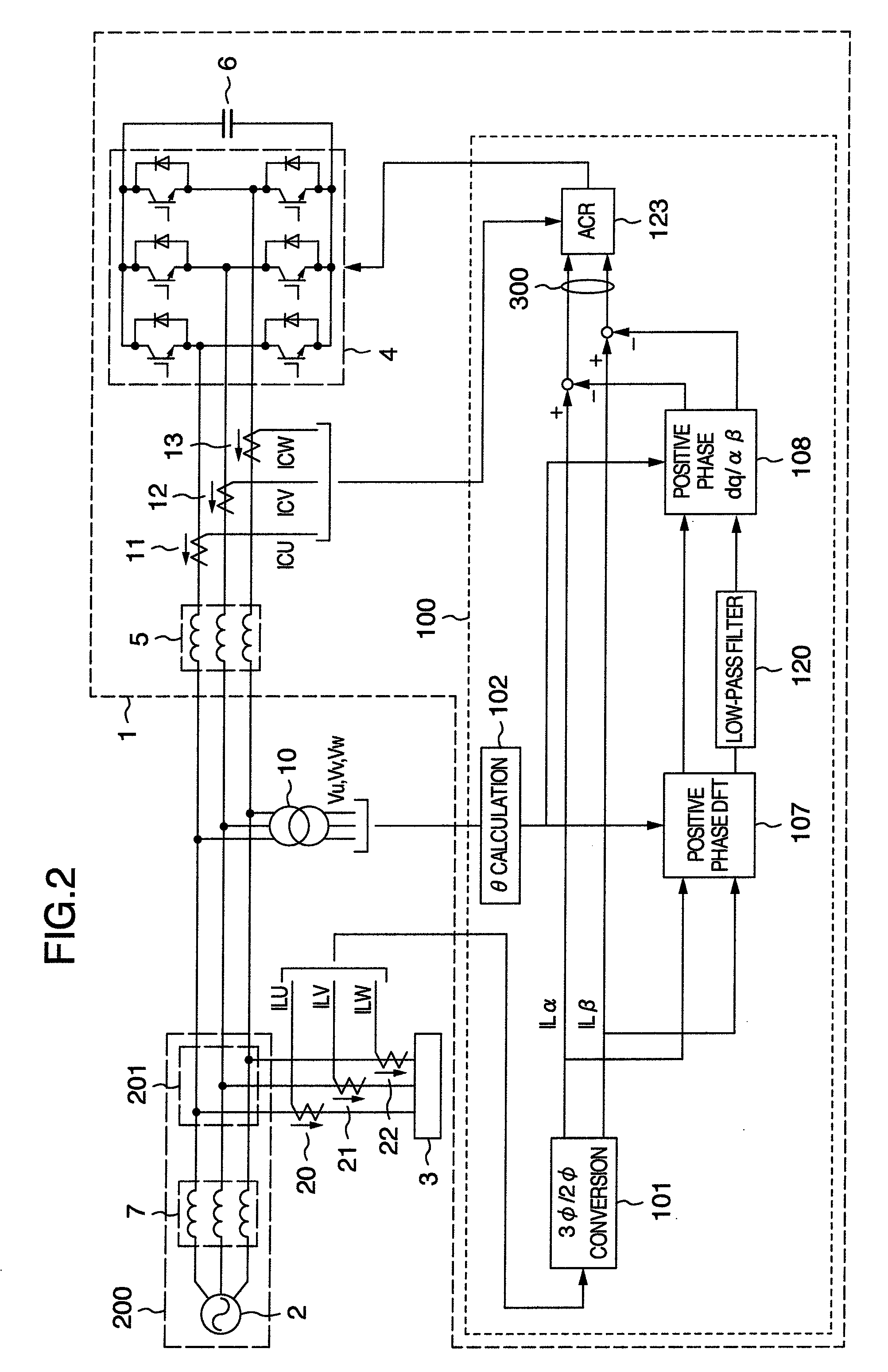
[0024]While the current instruction value 300 of the power converting device 1 is calculated in the first embodiment by subtracting the positive phase active fundamental current from the load current, the current instruction value 300 of a power converting device 1 of a second embodiment is calculated by subtracting not only the positive phase active fundamental current but also low-frequency components (frequency components sufficiently lower than the fundamental frequency) of the positive phase reactive current amplitude from the load current.

[0025]For example, in cases where fluctuation compensation in a relatively high-frequency range (over several Hz) is important, the output of the power converting device 1 against high-frequency fluctuations can be relatively increased by reducing the compensation for low-frequency components (e.g. under 1 Hz) of the reactive current amplitude.

[0026]FIG. 2 is a schematic diagram showing a principal part of the power converting de...

Example

Embodiment 3

[0030]While the current instruction value 300 of the power converting device 1 is obtained by subtracting the positive phase active fundamental current and the low-frequency components of the positive phase reactive fundamental current from the load current (ILα, ILβ) in the second embodiment, the current instruction value 300 of a power converting device 1 in accordance with a third embodiment is calculated by subtracting not only the positive phase active fundamental current and the low-frequency components of the positive phase reactive fundamental current but also low-frequency components of negative phase currents from the load current (ILα, ILβ).

[0031]In cases where the load 3 is an imbalanced load and fluctuation compensation to relatively high-frequency components (over several Hz) is important, the output of the power converting device 1 against high-frequency fluctuations can be relatively increased by reducing the compensation to negative phase low-frequency ...


PUM


Abstract

In a system to which a fluctuating load is connected, compensating for fluctuation in voltage harmonics at the load connecting point and fluctuation in system current harmonics has been difficult for a power converting device connected in parallel with the load. To resolve the problem, a power converting device connected in parallel with a fluctuating load includes: a Fourier series expansion unit which executes Fourier series expansion to load current by use of a reference sine wave in sync with a system and thereby outputs Fourier coefficients; and a fundamental component calculating unit which calculates a positive phase active fundamental component of the load current from the Fourier coefficients. A current instruction of the power converting device is generated by subtracting the fundamental current from the load current. With the current instruction, the fluctuations in system current harmonics and in voltage harmonics at the connecting point can be compensated for.

Description

BACKGROUND OF THE INVENTION[0001]The present invention relates to a power converting device which is connected to an AC (Alternating Current) system, and in particular, to a power converting device capable of suppressing voltage fluctuation caused by load fluctuation or suppressing fluctuation in system current.[0002]When a load connected to a system fluctuates, the system current fluctuates and a voltage drop caused by power line impedance and transformer impedance also fluctuates due to the system current fluctuation, by which voltage fluctuation (flicker) occurs at a connecting point where the load is connected to the system.[0003]A flicker suppressing device for suppressing the flicker has been proposed in JP-A-HEI 05-011870.[0004]The above flicker suppressing device calculates active current and reactive current from load current by use of a high-pass filter and a low-pass filter, respectively. The flicker suppressing device suppresses a fluctuating part of current flowing from...

Claims


Application Information

Patent Timeline
IPC IPC(8): H02M1/00
CPCY02E40/40H02J3/01
Inventor KATOH, SHUJIKIYOFUJI, YASUHIROKOSEKI, SHOICHIROITO, TOMOMICHIFUTAMI, MOTOO
Owner HITACHI IND PROD LTD
Why Eureka
Try Eureka