Rack-and-Pinion Steering Apparatus

a steering apparatus and rack and pinion technology, applied in mechanical devices, gearing, hoisting equipment, etc., can solve the problems of strict control of the pressurizing load of the pressurizing means, degrading the steering feeling, and difficult to execute micro adjustment of the steering operation, so as to reduce the friction of the meshing and stablely offer smooth and comfortable steering feeling over a long time.

Inactive Publication Date: 2008-09-18
JTEKT CORP
View PDF4 Cites 24 Cited by
  • Summary
  • Abstract
  • Description
  • Claims
  • Application Information

AI Technical Summary

Benefits of technology

[0012]The present invention has been conceived in view of the foregoing situation, with an object to provide a rack-and-pinion steering apparatus including pinion teeth having a larger pressure angle for reducing

Problems solved by technology

When the tooth specifications for such pinion teeth are selected under the standard pressure angle, the pinion teeth are so deeply meshed because of the pressurization by the pressurizing means, the meshing friction with the rack teeth is increased, which restrains propagation of a reaction force from the road surface to the driver operating the steering member connected to the pinion shaft, thus resulting in degradation of the steering feeling, which leads to a drawback that it becomes difficult to execute micro adjustment of the steering operation when driving at a high speed on a low-p road that provides only a small reaction force from the road surface and, therefore, to a disadvantage that the pressurizing load of the pressurizing means has to be strictly controlled.
Besides, the selected number of the pinion teeth is as few as 5 pieces, and therefore when such pinion teeth are meshed with the rack teeth, a phenomenon that the tip portion of a rack tooth that has passed the normal meshing position interferes with the dedendum of a pinion tooth as if gouging out the same, i.e. what is known as trochoid interference takes place, which further increases the meshing friction between the pinion teeth and rack teeth, thereby worsening the foregoing disadvantage.
Moreover, when the trochoid interference severely takes place, the wall thickness of the dedend

Method used


Image

  • Rack-and-Pinion Steering Apparatus
  • Rack-and-Pinion Steering Apparatus
  • Rack-and-Pinion Steering Apparatus

Examples


Embodiment Construction

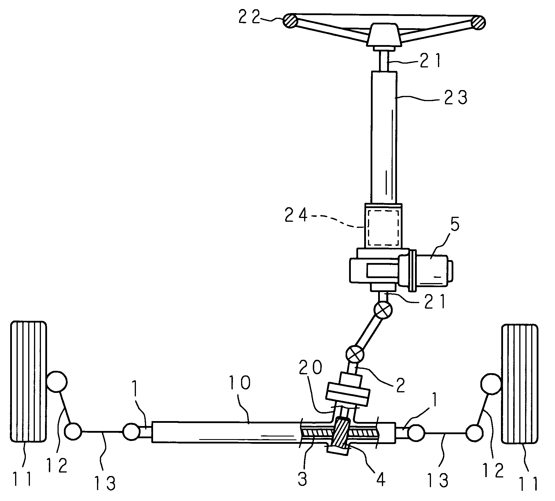
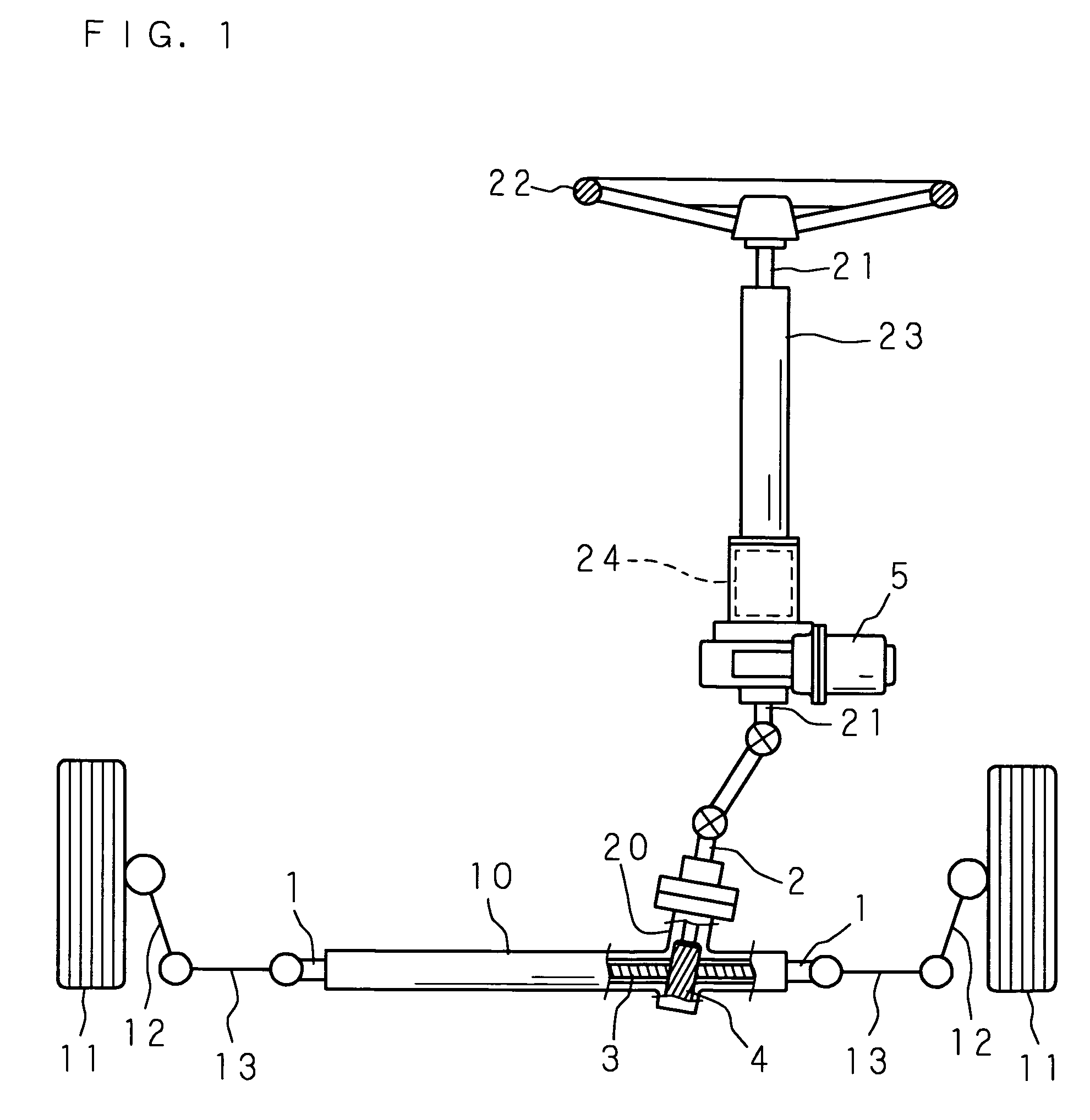
[0041]Hereunder, the present invention will be described in details, referring to the accompanying drawings showing the embodiments thereof. FIG. 1 is a schematic drawing showing an overall structure of a rack-and-pinion steering apparatus according to the present invention. In FIG. 1, numeral 1 designates a rack shaft, and the rack shaft 1 is movably supported in an axial direction thereof inside a cylindrical rack housing 10, so as to extend in a left and right direction of a vehicle body, which is not shown. The respective ends of the rack shaft 1 projecting from both sides of the rack housing 10 are connected to knuckle arms 12, 12 of the left and right front wheels 11, 11, serving as the wheels for steering, via respective tie rods 13, 13.

[0042]To a portion of the rack housing 10 close to a lateral end thereof, a pinion housing 20 is connected such that the central axes intersect with each other, and inside the pinion housing 20 a pinion shaft 2 is pivotably supported around it...


PUM


Abstract

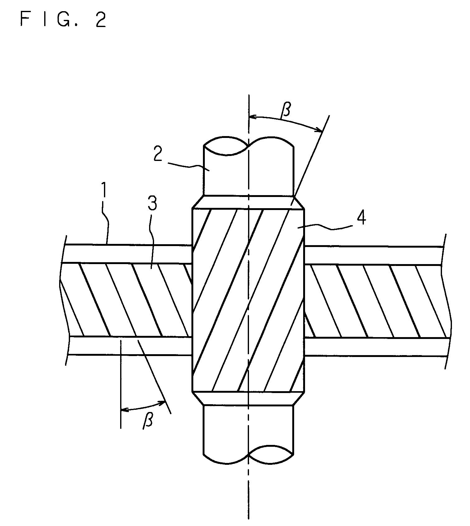
A rack-and-pinion steering apparatus comprises pinion teeth formed according to proper tooth specifications in other aspects under a larger pressure angle, thereby stably offering smooth and comfortable steering feeling over a long time. The module (m), number of teeth (z), tooth depth(h) and helix angle (β) of the pinion teeth (4) are set within the following ranges, under a pressure angle (α) set within a range of 24° to 30° and a given stroke ratio.
    • module (m): 1.8 to 2.0
    • number of teeth (z): 7 to 13
    • tooth depth (h): 2 m to 2.5 m
    • helix angle (β): 350 or smaller

Description

TECHNICAL FIELD[0001]The present invention relates to a rack-and-pinion steering apparatus, popularly employed as a type of steering apparatus for an automobile.BACKGROUND ART[0002]The rack-and-pinion steering apparatus popularly employed for an automobile is provided with a pinion shaft having pinion teeth provided on a circumferential surface thereof connected to a steering member such as a steering wheel, and a rack shaft having rack teeth provided over an appropriate length in a middle region of an outer surface thereof and disposed so as to extend in a left and right direction of the vehicle body, and converts the rotation of the pinion shaft according to operation of the steering member by the driver into an axial movement of the rack shaft, thus to steer the wheels for steering (generally, left and right front wheels) connected to the left and right ends of the rack shaft via respective tie rods.[0003]Regarding such rack-and-pinion steering apparatus, various proposals have b...

Claims


Application Information

Patent Timeline
IPC IPC(8): F16H1/04B62D3/12B62D5/22F16H19/04F16H55/08F16H55/18F16H55/28
CPCB62D3/12F16H55/0806Y10T74/18768Y10T74/19972Y10T74/1967
Inventor YAMAZAKI, TAKAYASUNAKANO, SHIROU
Owner JTEKT CORP
Why Eureka
Try Eureka