Rack-and-pinion steering apparatus

a steering apparatus and rack and pinion technology, applied in mechanical devices, gearing, hoisting equipment, etc., can solve the problems of strict control of the pressurizing load of the pressurizing means, degrading the steering feeling, and difficult to execute micro adjustment of the steering operation, so as to reduce the friction of the meshing and stablely offer smooth and comfortable steering feeling over a long time.

Inactive Publication Date: 2014-04-01
JTEKT CORP
View PDF20 Cites 4 Cited by
  • Summary
  • Abstract
  • Description
  • Claims
  • Application Information

AI Technical Summary

Benefits of technology

[0013]The present invention has been conceived in view of the foregoing situation, with an object to provide a rack-and-pinion steering apparatus including pinion teeth having a larger pressure angle for reducing meshing friction with rack teeth, and formed according to proper tooth specifications in other aspects under such pressure angle, thereby stably offering smooth and comfortable steering feeling over a long time.
[0019]According to the present invention, the pressure angle α of the pinion teeth provided on the pinion shaft is selected from the range of 24° to 30° which is sufficiently larger than the standard pressure angle, to reduce meshing friction under pressurization by the rack teeth, thus enabling smooth transmission. The upper limit of 30° of the pressure angle α is determined by processing restriction. Based on the pressure angle α and the stroke ratio thus selected, the module m and the number of teeth z are selected so as to satisfy geometrical requirements to secure a trochoid interference clearance and a tooth thickness of the addendum, as well as strength requirements to secure a bending strength of the dedendum and a fatigue strength of the tooth surface. At the same time, a tooth depth h is selected so as to reduce an addendum modification and slippage fluctuation at the mesh portion, and also a helix angle β is selected so as to alleviate a load on a supporting bearing of the pinion shaft thus determining the tooth specifications, and enabling smooth and assured transmission to the rack shaft provided with the rack teeth meshed without backlash, thus achieving comfortable steering feeling.
[0021]According to these inventions, the tooth surface modification including one or both of the correction of the pressure angle in a direction of the tooth profile and the crowning in the tooth trace direction is introduced, so as to improve the tooth bearing that causes fluctuation in torque during the steering operation, thereby improving the steering feeling and leveling off the abrasion of the tooth surface to compensate the degradation in strength of the pinion teeth.
[0023]According to this invention, the pinion teeth formed according to the foregoing tooth specifications are employed in the electric power steering apparatus, in which both the operating force applied to the steering member by the driver and the force generated by the motor are applied to the mesh portion between the pinion teeth and the rack teeth, to thereby minimize the risk of breakdown of the teeth and to prevent degradation in response caused by the impact of the meshing friction, thus achieving comfortable steering feeling.
[0024]In the rack-and-pinion steering apparatus according to the present invention, properly selecting the tooth specifications of the pinion teeth provided on the pinion shaft enables the pinion teeth to mesh with the rack teeth provided on the rack shaft without backlash, under optimally minimized meshing friction and without incurring trochoid interference, thereby stably offering smooth and comfortable steering feeling over a long time. Thus, the present invention provides excellent benefits.

Problems solved by technology

When the tooth specifications for such pinion teeth are selected under the standard pressure angle, the pinion teeth are so deeply meshed because of the pressurization by the pressurizing means, the meshing friction with the rack teeth is increased, which restrains propagation of a reaction force from the road surface to the driver operating the steering member connected to the pinion shaft, thus resulting in degradation of the steering feeling, which leads to a drawback that it becomes difficult to execute micro adjustment of the steering operation when driving at a high speed on a low-μ road that provides only a small reaction force from the road surface and, therefore, to a disadvantage that the pressurizing load of the pressurizing means has to be strictly controlled.
Besides, the selected number of the pinion teeth is as few as 5 pieces, and therefore when such pinion teeth are meshed with the rack teeth, a phenomenon that the tip portion of a rack tooth that has passed the normal meshing position interferes with the dedendum of a pinion tooth as if gouging out the same, i.e. what is known as trochoid interference takes place, which further increases the meshing friction between the pinion teeth and rack teeth, thereby worsening the foregoing disadvantage.
Moreover, when the trochoid interference severely takes place, the wall thickness of the dedendum of the pinion teeth is reduced over time by the friction with the tip portion of the rack teeth, which leads to degradation in strength of the pinion teeth, and even to premature breakdown before a desired life span is completed.
Therefore, the pinion teeth are more likely to breakdown, and besides the response of the rack shaft, upon transmitting thereto the rotation of the motor via the pinion shaft, becomes less perceptible, thus resulting in degradation in steering feeling.
Japanese Examined Patent Application Laid-Open No. 62-38579 (1987) only discloses a method of selecting a helix angle and a pressure angle of the rack teeth based on a relation with the cross-sectional shape of the rack shaft, for the purpose of preventing seizure between the pinion teeth and the rack teeth formed as skewed teeth, which occurs at the mesh portion therebetween because of the rotational displacement of the rack shaft around its axis, and hence does not provide any measures to solve the foregoing problems originating from the meshing friction and the trochoid interference.
In this case, however, it becomes difficult to achieve a transverse contact ratio of 1 or greater between the rack teeth and the pinion teeth, and hence the meshing becomes discontinuous, thus creating another drawback that smooth movement of the rack shaft for the steering operation is disturbed.

Method used


Image

  • Rack-and-pinion steering apparatus
  • Rack-and-pinion steering apparatus
  • Rack-and-pinion steering apparatus

Examples


Embodiment Construction

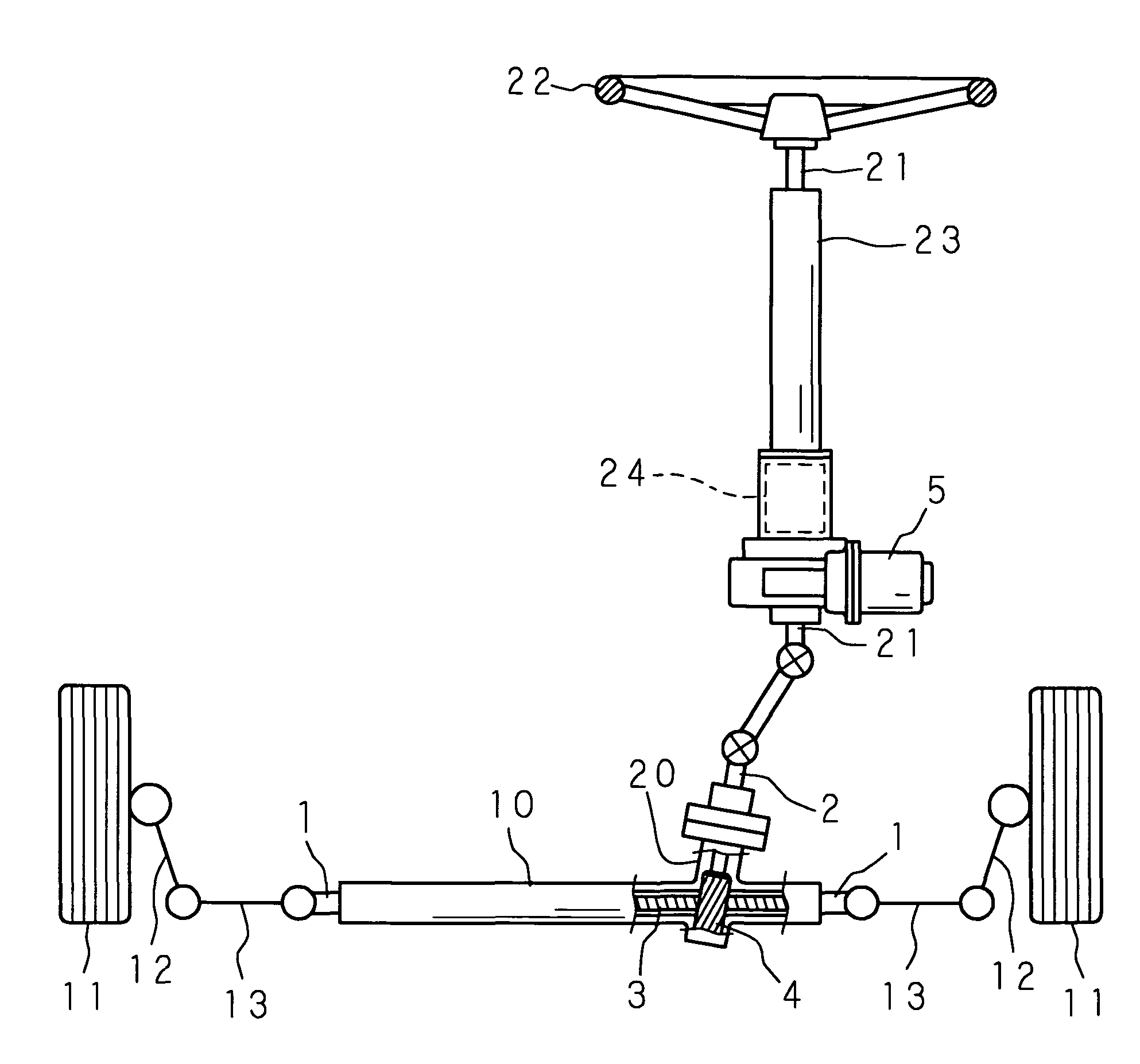
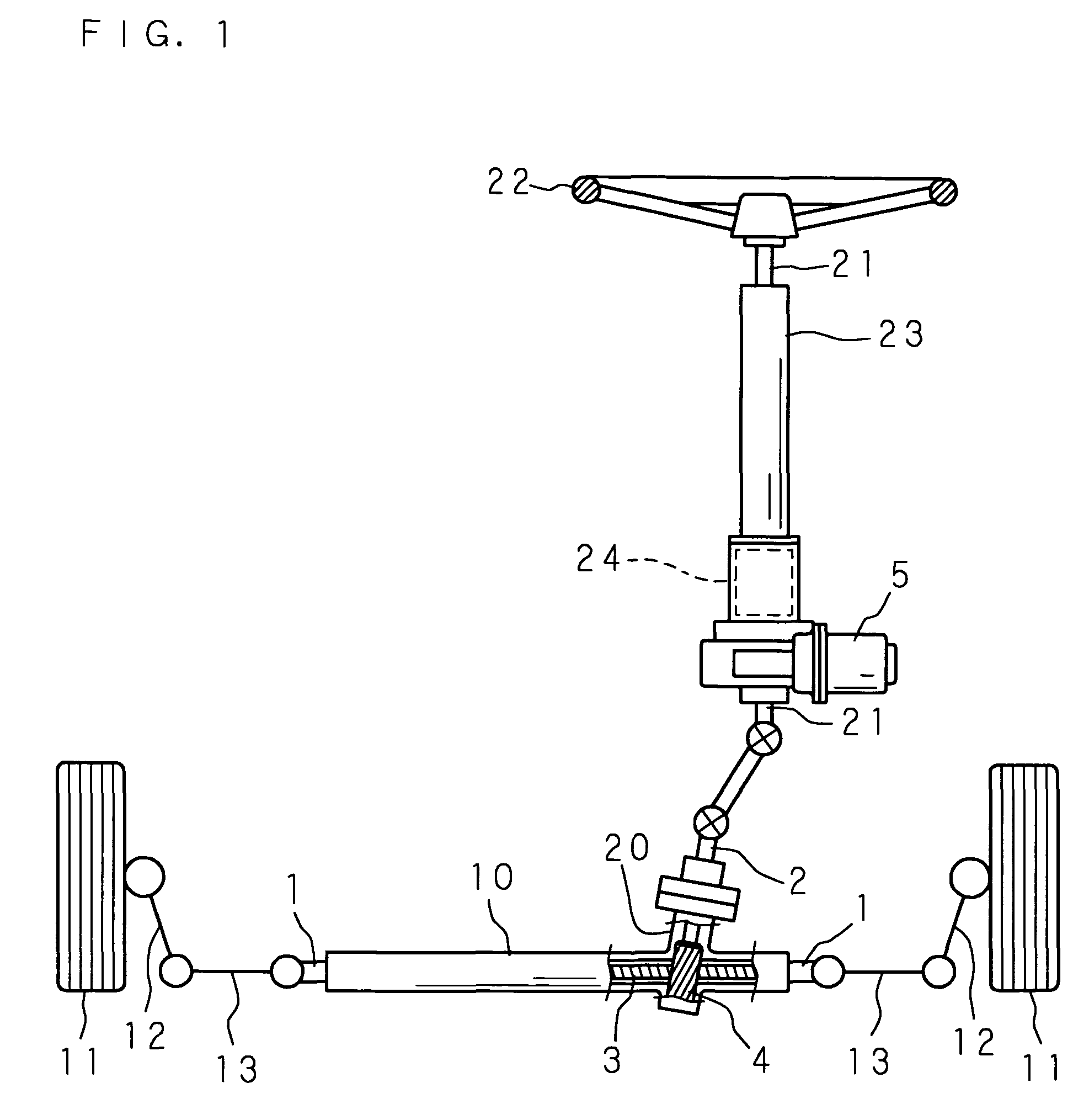
[0042]Hereunder, the present invention will be described in details, referring to the accompanying drawings showing the embodiments thereof. FIG. 1 is a schematic drawing showing an overall structure of a rack-and-pinion steering apparatus according to the present invention. In FIG. 1, numeral 1 designates a rack shaft, and the rack shaft 1 is movably supported in an axial direction thereof inside a cylindrical rack housing 10, so as to extend in a left and right direction of a vehicle body, which is not shown. The respective ends of the rack shaft 1 projecting from both sides of the rack housing 10 are connected to knuckle arms 12, 12 of the left and right front wheels 11, 11, serving as the wheels for steering, via respective tie rods 13, 13.

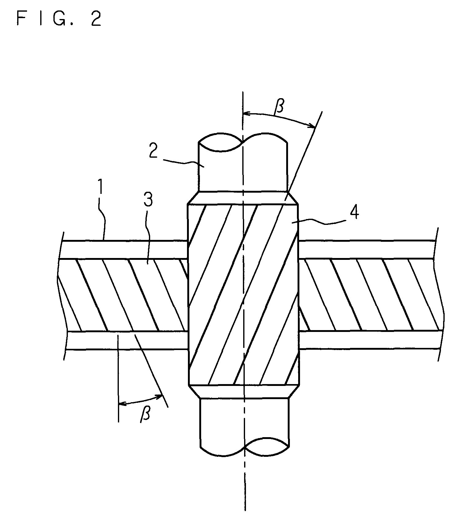
[0043]To a portion of the rack housing 10 close to a lateral end thereof, a pinion housing 20 is connected such that the central axes intersect with each other, and inside the pinion housing 20 a pinion shaft 2 is pivotably supported around it...


PUM


Abstract

A rack-and-pinion steering apparatus comprises pinion teeth formed according to proper tooth specifications in other aspects under a larger pressure angle, thereby stably offering smooth and comfortable steering feeling over a long time. The module (m), number of teeth (z), tooth depth (h) and helix angle (β) of the pinion teeth (4) are set within the following ranges, under a pressure angle (α) set within a range of 24° to 30° and a given stroke ratio.module (m): 1.8 to 2.0number of teeth (z): 7 to 13tooth depth (h): 2 m to 2.5 mhelix angle (β): 35° or smaller

Description

[0001]This application is the national phase under 35 U.S.C. §371 of PCT International Application No. PCT / JP2005 / 000251 which has an International filing date of Jan. 12, 2005 and designated the United States of America.TECHNICAL FIELD[0002]The present invention relates to a rack-and-pinion steering apparatus, popularly employed as a type of steering apparatus for an automobile.BACKGROUND ART[0003]The rack-and-pinion steering apparatus popularly employed for an automobile is provided with a pinion shaft having pinion teeth provided on a circumferential surface thereof connected to a steering member such as a steering wheel, and a rack shaft having rack teeth provided over an appropriate length in a middle region of an outer surface thereof and disposed so as to extend in a left and right direction of the vehicle body, and converts the rotation of the pinion shaft according to operation of the steering member by the driver into an axial movement of the rack shaft, thus to steer the ...

Claims


Application Information

Patent Timeline
Patent Type & Authority Patents(United States)
IPC IPC(8): F16H55/28B62D5/22B62D3/12F16H55/18F16H19/04F16H55/08
CPCB62D3/12F16H55/0806Y10T74/1967Y10T74/19972Y10T74/18768
Inventor YAMAZAKI, TAKAYASUNAKANO, SHIROU
Owner JTEKT CORP
Why Eureka
Try Eureka