

Shunt resistor and method for manufacturing the same
a resistor and resistor technology, applied in the field of current detecting resistors, can solve the problems of inability to accurately detect current, unsuitable plate-shaped resistance body shown in the patent publication, and difficulty in accurately detecting current upon the current including high-frequency components, so as to reduce the current flux band and reduce the effect of changing the resistance value by skin effect by high-frequency curren
- Summary
- Abstract
- Description
- Claims
- Application Information
AI Technical Summary
Benefits of technology
Problems solved by technology
Method used
Image

Examples
first embodiment
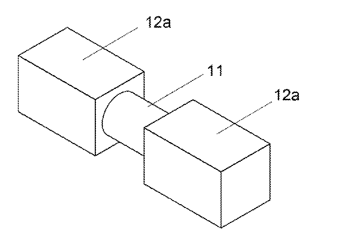
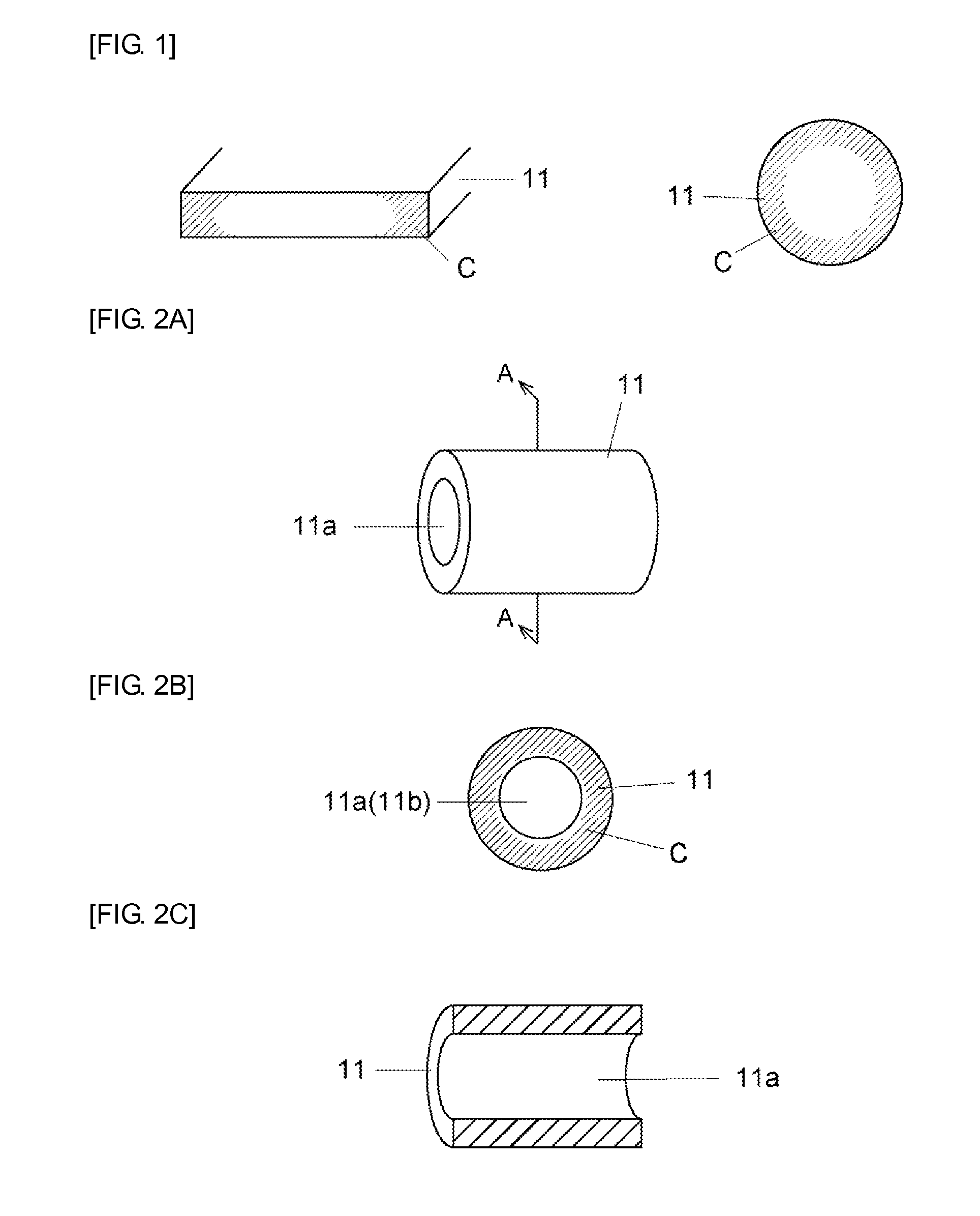
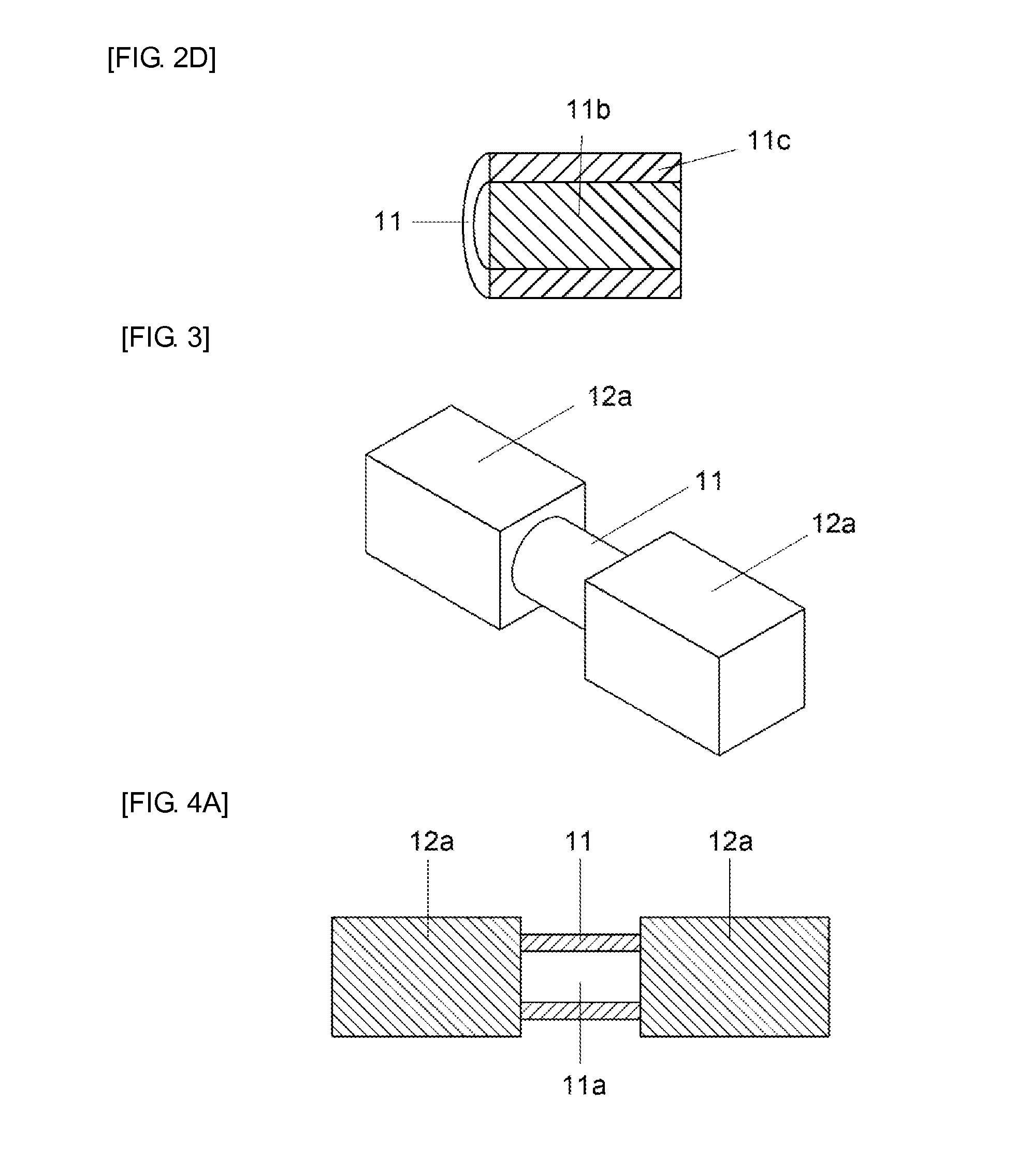
[0029]FIG. 3 shows external appearance of the resistor of first embodiment of the invention, and FIGS. 4A-4C respectively shows structural features of resistance body and electrode by section-views along their axis of the resistor. External appearance of the resistor in FIGS. 4A-4C respectively is same with the structure shown in FIG. 3. The resistor is a shunt resistor, which comprises rod-shaped resistance body 11 and square pillar-shaped main electrodes 12a, 12a of another material from the resistance body connected to both end faces of the resistance body. And, resistance body 11 consists of pipe-shaped structure to have a hole 11a that goes through in direction where main electrodes 12a, 12a are disposed as shown in FIGS. 4A-4C.
[0030]Since main electrode 12a is square pillar-shaped according to the resistor of the embodiment, the resistor has a feature that it is easy to mount by surface mounting etc. and easy to treat when manufacturing. As to structure 1 of fixing resistance ...
second embodiment
[0034]FIG. 5 shows the resistor of second embodiment of the invention, and FIG. 6 shows its cross-section. The resistor is a shunt resistor that cylinder-shaped (pipe-shaped) main electrodes 12b,12b, which is another material from the resistance body, are fitted and bonded with both end portions of pipe-shaped resistance body 11. And, resistance body 11 consists of pipe-shaped structure that has a hole 11 a going through in direction where main electrodes 12b,12b are disposed as shown in FIG. 6.
[0035]In this embodiment, pipe-shaped structure of main electrode 12b is used as well as resistance body 11. Inside diameter of the hole of main electrode 12b is almost same to outside diameter of resistance body 11. End portion of the resistance body fits into the hole of the main electrode, and fixed by above-mentioned fixation method. Moreover, it is acceptable that making inside diameter of the hole of the resistance body almost same to outside diameter of the main electrodes, and main el...
third embodiment
[0041]FIG. 8 shows a shunt resistor of third embodiment of the invention. The shunt resistor 10 comprises cylindrical resistance body 11 of resistance alloy material such as Manganin etc, a pair of columnar main electrode 12,12 of high electric conductivity metal material such as copper etc, which is another material from the resistance body, and a pair of plate-shaped voltage detecting electrode 13,13 of high electric conductivity metal material such as copper etc, which is another material from the main electrode. The voltage detecting electrode 13 has detecting terminal 13a, which is protruding from the detecting electrode 13, and terminal of voltage detecting circuit is connected to the terminal 13a by welding etc.
[0042]As shown in FIG. 8, voltage detecting electrode 13 is disposed between resistance body 11 and main electrode 12. And, end face of plate-shaped voltage detecting electrode 13 and end face of columnar main electrode 12 are fixed so as to oppose respectively to both...
PUM
| Property | Measurement | Unit |
|---|---|---|
| Electrical resistance | aaaaa | aaaaa |
| Circumference | aaaaa | aaaaa |
Abstract
Description
Claims
Application Information