Multi-functional electrical vaporizer for a liquid substance and method of manufacturing such a vaporizer

a multi-functional, electrical vaporizer technology, applied in the direction of air humidification system, heating type, lighting and heating apparatus, etc., can solve the problems of increasing the difficulty of manufacturing, reducing production costs, and affecting the quality of vaporizers

Inactive Publication Date: 2005-07-12
SC JOHNSON & SON INC
View PDF37 Cites 112 Cited by
  • Summary
  • Abstract
  • Description
  • Claims
  • Application Information

AI Technical Summary

Benefits of technology

[0009]In conceiving our invention, we realized that the foregoing problem could be addressed only by radically departing from the conventional wisdom of producing and maintaining large inventories of diverse devices, and, instead, developing a new line of vaporizers having a universal core housing structure that can easily accommodate any of several different functional devices and external designs.

Problems solved by technology

Such diversity in the marketplace causes considerable problems for the manufacturers of these vaporizers, who, on the one hand, must produce different models tailored to meet the specific requirements of each market, yet, on the other hand, are under considerable pressure to reduce production costs in order to keep pace with their competitors.
Rather, a more difficult problem for manufacturers has to do with the varying market preferences as to which additional functional capabilities the vaporizer should be equipped with.
Aesthetic appearance is also an important issue with vaporizers, especially wall-mounted ones that are often visibly displayed in one's home or place of work.
Producing and maintaining large inventories, however, prevents manufacturers from reducing their production costs and creates a formidable barrier to further market expansion.

Method used


Image

  • Multi-functional electrical vaporizer for a liquid substance and method of manufacturing such a vaporizer
  • Multi-functional electrical vaporizer for a liquid substance and method of manufacturing such a vaporizer
  • Multi-functional electrical vaporizer for a liquid substance and method of manufacturing such a vaporizer

Examples


Embodiment Construction

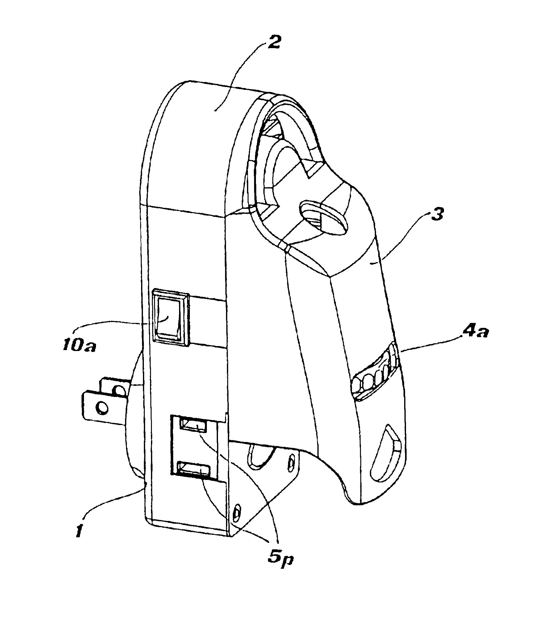
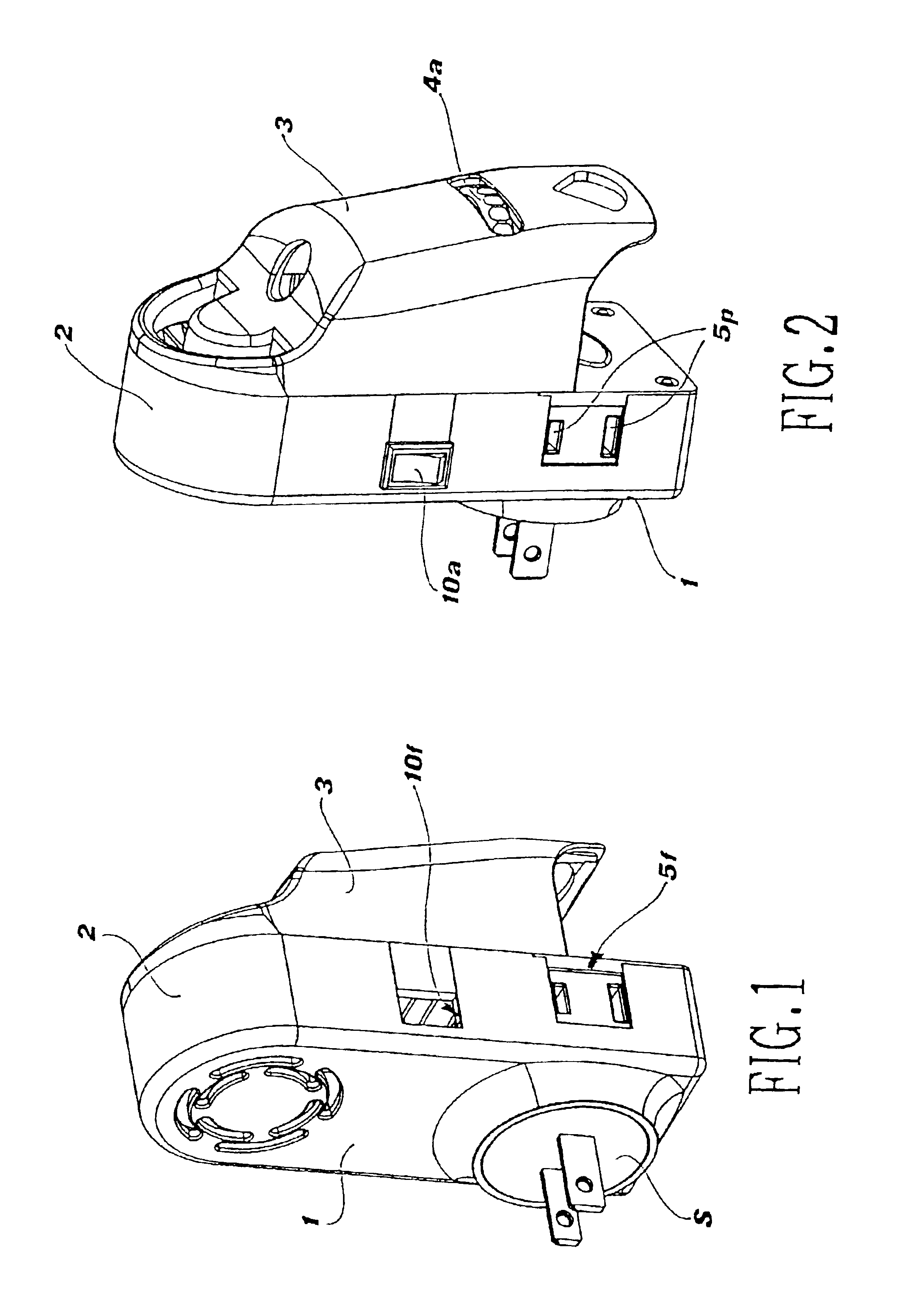
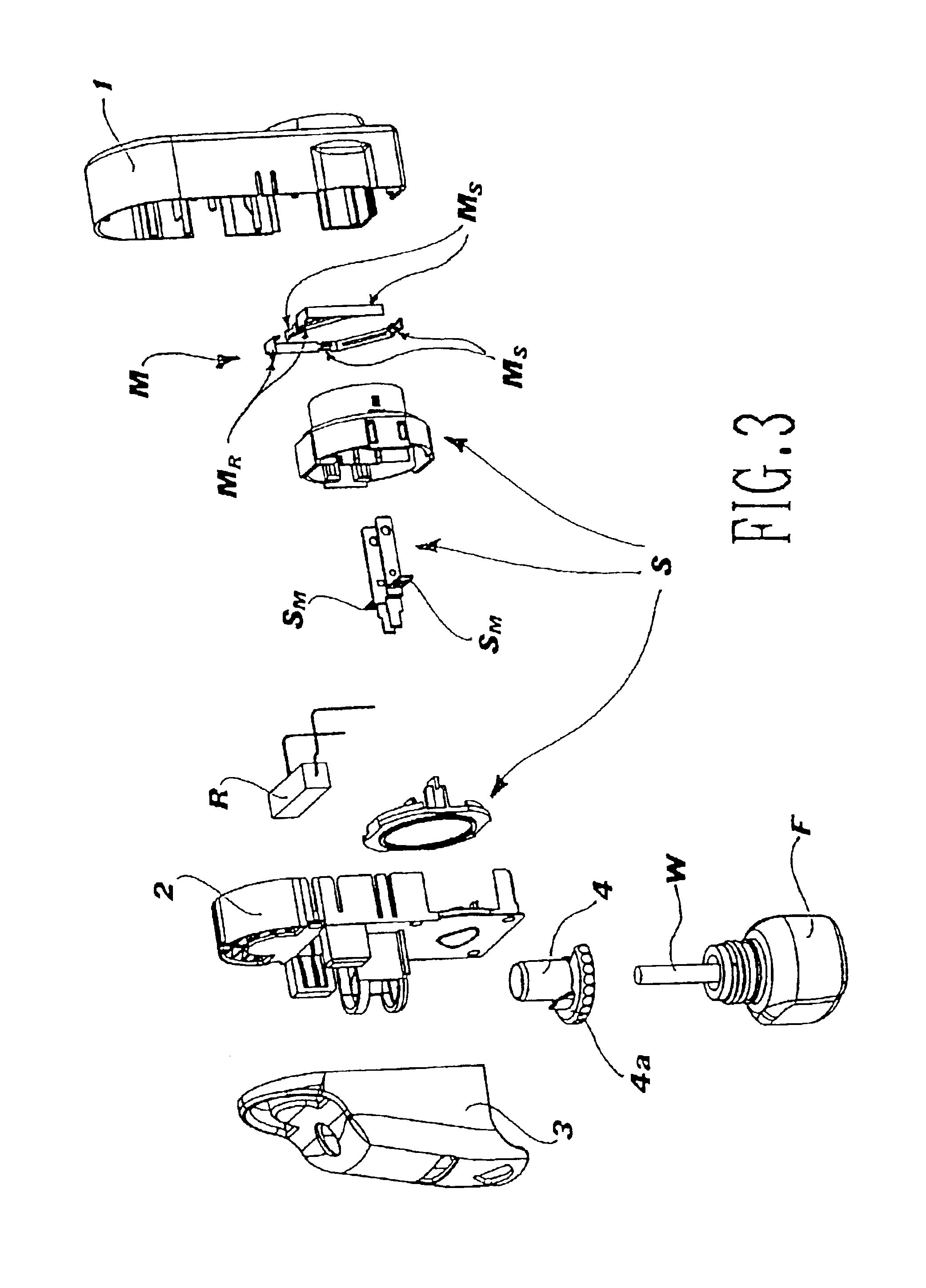
[0027]FIGS. 1-7 illustrate a vaporizer according to a first preferred embodiment of our invention. The vaporizer includes a first shell 1 and a second shell 2 that can be joined together in any well-known manner, including rivets, screws, heat-staking, or the like. The first and second shells 1 and 2 together form the core housing structure of the vaporizer. The housing structure contains many of the basic functional components of the vaporizer, as well as one or more additional functional devices. Basic components of the vaporizer include a rotatable electrical plug assembly S, a contact carrier M having several electrical contacts, an electrical heating device R connected to a pair of contacts MR of the contact carrier M, a bottle F containing the liquid substance to be evaporated, and a wick W for drawing the liquid substance out of the bottle and toward an upper portion of the wick.

[0028]The plug assembly S is of the sliding-contact type and has contacts SM for engagement with e...


PUM

PropertyMeasurementUnit
flexibleaaaaaaaaaa
housing structureaaaaaaaaaa
distanceaaaaaaaaaa

Abstract

A multi-functional electrical vaporizer for a liquid substance includes a bottle for holding the liquid substance, a wick for drawing the liquid substance out of the bottle, an electrical heating device positioned proximate to an upper portion of the wick, an electrical plug assembly, an electrical circuit for powering the electrical heating device, a housing structure with respect to which the bottle is detachably secured and in which at least the electrical plug assembly, the electrical circuit, and the electrical heating device are disposed, and a cover that is joined to and at least partially covers the housing structure. The housing structure, which includes a first shell and a second shell that are joined together, is configured to receive any of a plurality of different additional functional devices. The cover is provided with at least one access window corresponding to whatever additional functional device the housing structure is to be equipped with.

Description

BACKGROUND OF THE INVENTION[0001]1. Field of the Invention[0002]Our invention relates generally to an electrical vaporizer for a liquid substance, such as an aromatic liquid, an insecticide, or the like. In particular, our invention relates to a multi-functional vaporizer that, in addition to performing the basic function of vaporizing the liquid substance by means of an electrical heating device, can also be equipped with one or more additional functional devices, such as a draft regulator, a wick adjustment mechanism, a fan, a night light, an indicator light, a programmable user interface, or the like.[0003]2. Description of the Related Art[0004]The worldwide market for electrical vaporizers for use with aromatic liquids, insecticides, and the like is extremely diverse both with respect to the technical specifications of the electrical components of the vaporizer and with respect to the functional capabilities demanded by users. Such diversity in the marketplace causes considerabl...

Claims


Application Information

Patent Timeline
Patent Type & Authority Patents(United States)
IPC IPC(8): A01M1/20A01M13/00A61L9/015A61L9/03F24F6/08F24F6/02F24F6/10
CPCA61L9/037A61L2209/12
Inventor PEDROTTI, ANDREAZOBELE, FRANCOCAMPEDELLI, PAOLOBALDESSARI, STEFANO
Owner SC JOHNSON & SON INC
Why Eureka
Try Eureka