Folding knife light tool

a technology of light tools and folding knives, applied in portable power-driven tools, instruments, lighting and heating equipment, etc., can solve the problem of no knife currently availabl

Inactive Publication Date: 2006-03-07
ZIRK JASON E +1
View PDF53 Cites 30 Cited by
  • Summary
  • Abstract
  • Description
  • Claims
  • Application Information

AI Technical Summary

Benefits of technology

[0011]It is still yet another object to provide a tool and a process of manufacturing tools endowed with an ability to enable a user to locate the knife in the dark, if desired.
[0012]It is a further o...

Problems solved by technology

No knife is currently available that allows the user to choose to operate the flashlight with...

Method used


Image

  • Folding knife light tool
  • Folding knife light tool
  • Folding knife light tool

Examples


Embodiment Construction

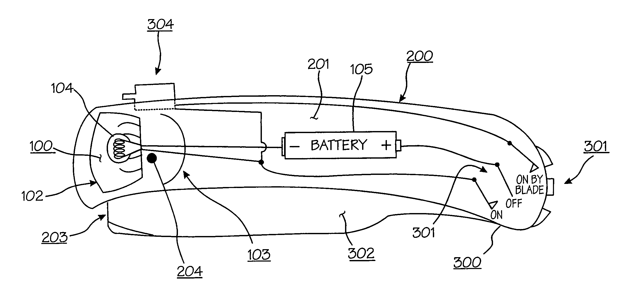
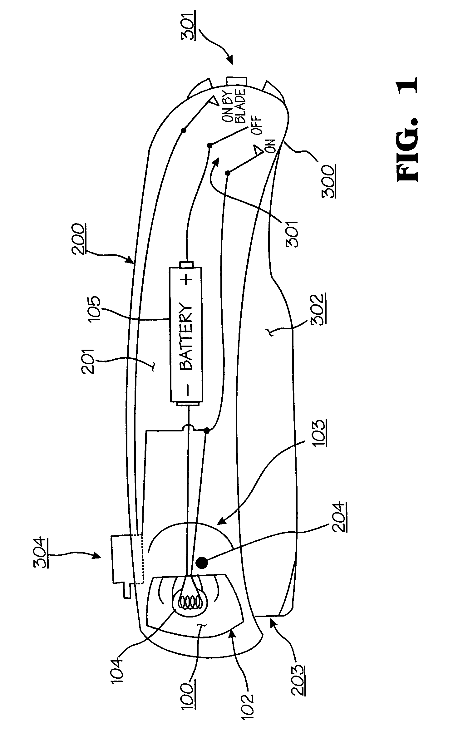
[0032]With reference to FIG. 1, the folding knife flashlight tool is shown in one embodiment in a folded position. The illuminating component 100, housing component 200, and the blade-switch component 300 comprise the three major components of this embodiment. A illiminator 104 is located behind a lens 102 and in front of a reflector 103 at the pivot axis 204 end of the housing 200. The housing 200 has an ergonometric shape for comfort in usage. The lens 102 can be of a focusing type which is adjustable by any of the adjusting means available in the trade. In another embodiment illustrated by FIG. 5A, a lens 102 is provided on both sides of the extended is blade 302 wherein both sides of the blade 302 are illuminated

[0033]Referring to FIGS. 1 and 4, a three position waterproof mode switch 301 is positioned at the end of the housing 200 opposite of the light end. Three modes of operation are provided: OFF, ON, and ON-by-blade. In an embodiment of this invention illustrated by FIG. 6,...


PUM


Abstract

A folding knife light tool with an ergonometric handle in which an illuminating means whether an LED or light bulb or a laser light is incorporated into the handle housing in the spaces existing between the blade, the locking mechanism, and the handle. A knife handle is provided having a body contoured for the hand. The housing is made from one molded piece with a slit in the middle. The handle includes a pivot point for supporting a blade between the longitudinal sides or scales of the blades. A conventional locking or non-locking system is utilized for keeping the blade open once it is unfolded. When the blade is folded, a portion of the blade extends above the sides of the knife handle for digital engagement in the opening operation.

Description

CLAIM OF PRIORITY[0001]This application makes reference to, incorporates the same herein, and claims all benefits accruing under 35 U.S.C. §119 from my provisional application SINGLE BODY MULTI-TOOL DEVICE filed with the U.S. Patent & Trademark Office on 3rd Mar. 2003 and there duly assigned Ser. No. 60 / 451,544.BACKGROUND OF THE INVENTION[0002]1. Technical Field[0003]The present invention relates generally to folding knives and processes for manufacturing knives, and more specifically to a folding knife incorporating a source of selectively operable illumination.[0004]2. Related Art[0005]Many different types of folding knives are available. Exemplary knives provided with lighting fixtures may be found in such references as U.S. Pat. No. 4,364,104 to Holahan et al., entitled NOVELTYLIGHT, issued on Dec. 14, 1982; U.S. Pat. No. 5,313,376 to McIntosh, entitled MULTIPURPOSEKNIFE / LIGHT, issued on May 17, 1994; U.S. Pat. No. 5,467,256 to Chen, entitled KNIFE WITH LIGHTING FIXTURE, issued ...

Claims


Application Information

Patent Timeline
IPC IPC(8): B25B23/18B26B1/00B26B1/04B26B11/00B43K23/00B43L7/00B43L7/10B43L12/00B43L12/02B43L13/00B43L13/02B43L23/08F21V33/00G01B3/10
CPCB26B1/04B26B11/008B43K23/001B43L7/005B43L7/10B43L12/02B43L13/002B43L23/08F21V33/0084B43L12/00G01B3/1084
Inventor ZIRK, JASON E.KADY, DARREN
Owner ZIRK JASON E
Why Eureka
Try Eureka