3D image acquisition apparatus and 3D image acquisition method

a technology of image acquisition and image acquisition method, which is applied in the field of 3d (three dimensional) image acquisition method, can solve the problems of difficult image feature correspondence, time and precision measurement, and the inability to measure the shape of objects without textur

Inactive Publication Date: 2006-03-14
OLYMPUS CORP
View PDF8 Cites 101 Cited by
  • Summary
  • Abstract
  • Description
  • Claims
  • Application Information

AI Technical Summary

Problems solved by technology

The former is a theoretically ideal method because there is no dead angle, but it has problems with measured time and precision.
The passive stereo method, however, has drawbacks that the correspondence of features in the images is difficult and the shape of an object without texture cannot be measured.
However, in order to measure the shape of the entire area of the object, image input needs to be repeated a number of times by scanning projection light, and a great deal of time is required.
As the pattern shape encoding, a method using a distribution of opening width of a slit and a method using an M-series encoding have been proposed, but these are less practical because of problems with measurement density and stability of measurement.
However, either method has a drawback that the number of recognizable gradations is small.
Consequently, extraction of a matrix s

Method used


Image

  • 3D image acquisition apparatus and 3D image acquisition method
  • 3D image acquisition apparatus and 3D image acquisition method
  • 3D image acquisition apparatus and 3D image acquisition method

Examples


first embodiment

(First Embodiment)

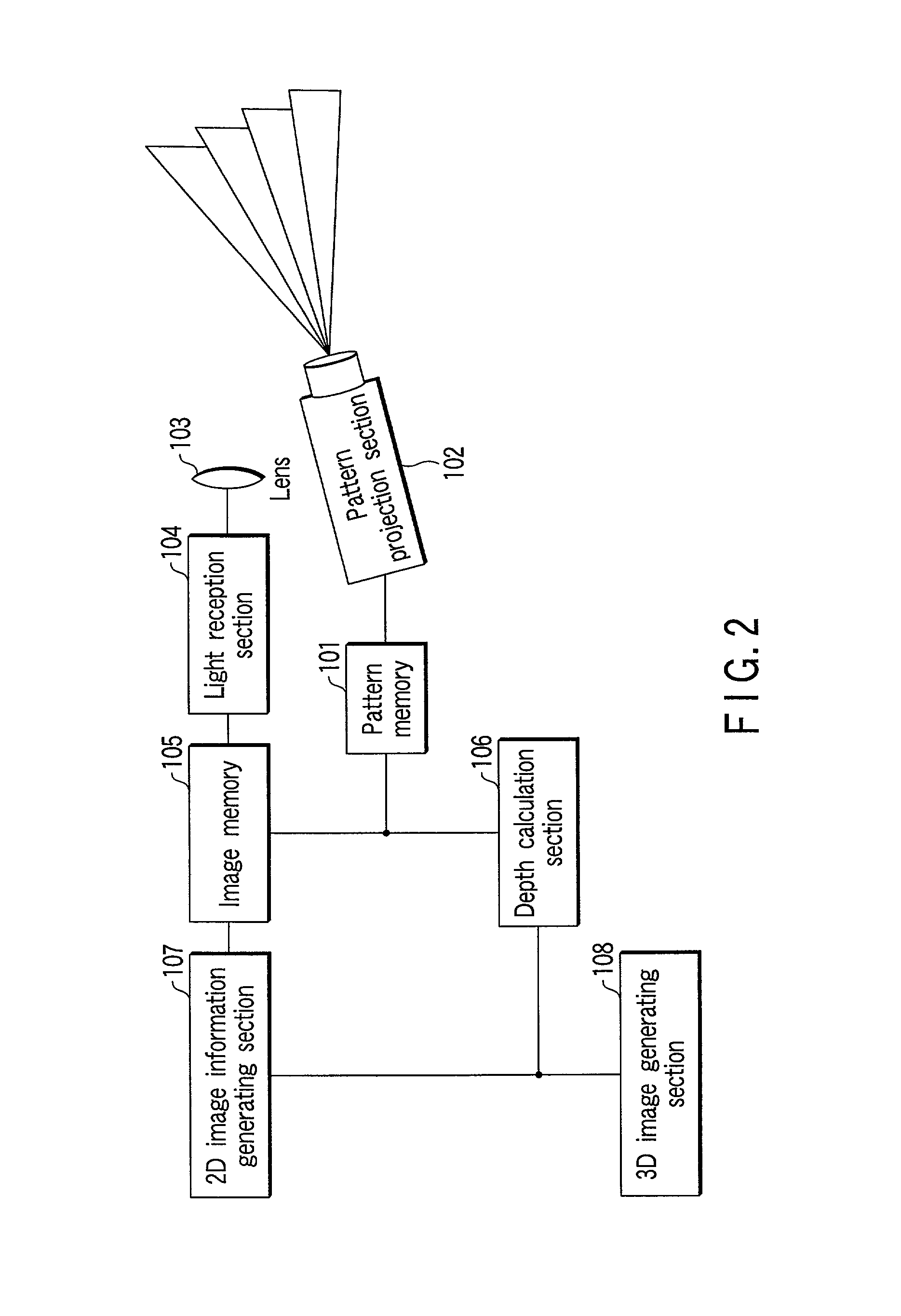
[0051]A first embodiment of the invention will now be described in detail with reference to FIGS. 1–3.

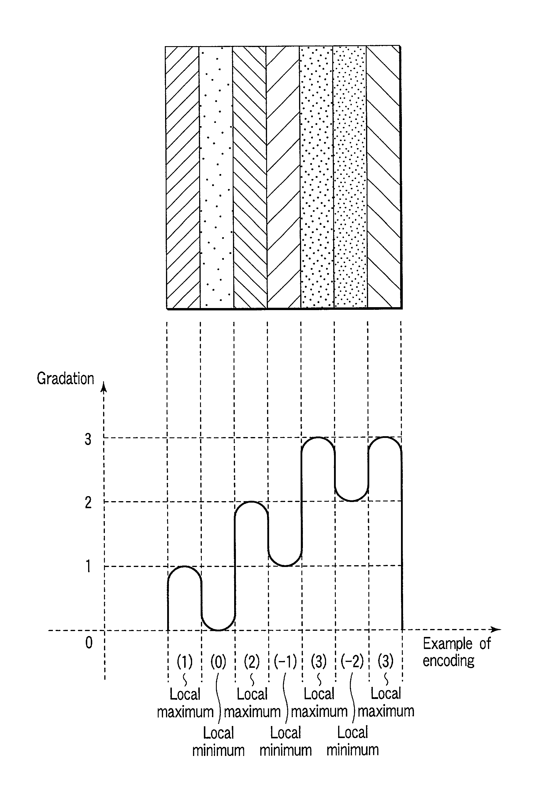
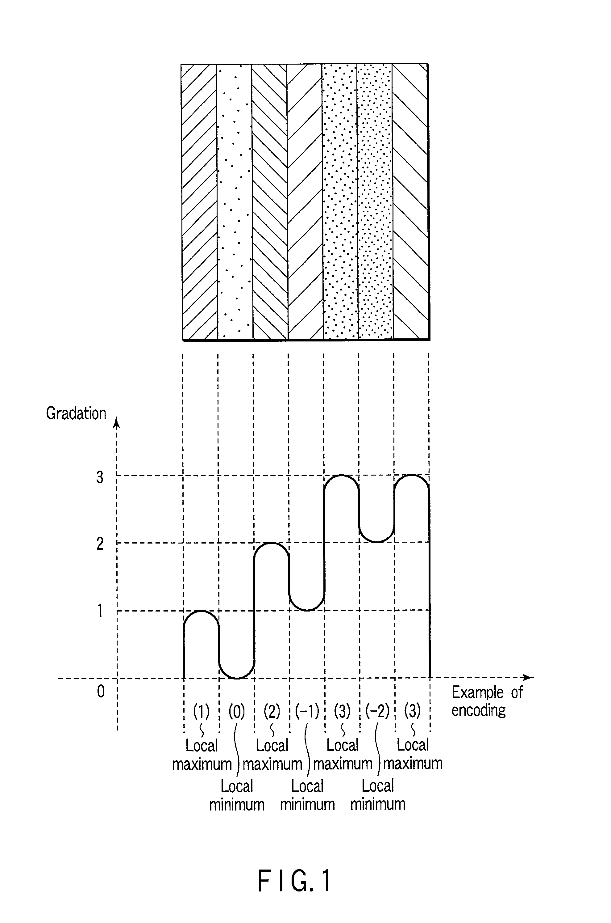
[0052]In order to describe a pattern light projection method for spatial pattern encoding according to the first embodiment, FIG. 1 shows a four-gradation stripe pattern by way of example. This pattern is a predetermined light pattern which is projected on an object when a 3D image of the object is to be acquired, for example, in order to measure the shape of the object.

[0053]This predetermined pattern comprises a plurality of areas (stripes in FIG. 1) each having a substantially constant luminance value. The luminance (gradation) of each area belongs to any one of predetermined luminances (gradations). In FIG. 1, each stripe belongs to any one of four gradations (0, 1, 2, 3). In this example, pattern areas having local maximum luminance values and local minimum luminance values are alternately arranged.

[0054]Each area is arranged such that if one of its adjacent a...

second embodiment

(Second Embodiment)

[0074]A second embodiment of the present invention will now be described with reference to FIG. 4. The second embodiment is substantially similar to the first embodiment shown in FIG. 2 with respect to the spatial pattern encoding method. However, as shown in FIG. 4, the structure of the 3D image acquisition apparatus is different, as described below. The imaging means are provided at a plurality of locations with different viewpoints, for example, on the right and left sides (two locations) of the pattern projection section 202. Accordingly, a pair of image memories are provided on the right and left sides. Moreover, means for determining the right-and-left correspondency is additionally provided.

[0075]More specifically, the 3D image acquisition apparatus according to the second embodiment comprises a pattern memory 201 storing a predetermined projection-light pattern; a pattern projection section 202 for projecting the pattern light on the object; light collecti...

third embodiment

(Third Embodiment)

[0083]A third embodiment of the present invention will now be described with reference to FIGS. 5 and 6.

[0084]The structure of the 3D image acquisition apparatus used in the first embodiment is substantially the same as that of the 3D image acquisition apparatus of the third embodiment. However, the spatial pattern encoding method is different, as shown in FIG. 5.

[0085]FIG. 5 shows an example of a stripe pattern in which local maximums / minimums of a plurality of color signals are aligned. Gray scale values are used in the structure of the pattern adopted in the first embodiment. On the other hand, the pattern used in the third embodiment is a pattern of respective color components (R, G, B), and areas with local maximum luminance values and areas with local minimum luminance values are aligned. As is shown in FIG. 5, in the color stripe pattern, local maximum positions and local minimum positions of RGB are aligned.

[0086]R, G and B signals are individually encoded,...


PUM


Abstract

A 3D image acquisition apparatus comprises a pattern projection section which projects a pattern on an object to be measured, an imaging section which is disposed at a distance from the pattern projection section and images the object on which the pattern has been projected, and a depth calculation section which detects the projection pattern projected on the object on the basis of an image acquired by the imaging section, collates the detected pattern and the projected pattern, and calculates a depth of respective parts of the object on the basis of the correspondency of the collation. The projected pattern is stripes/matrix formed by alternately arranging areas with local maximum/minimum luminance values. Thus, stripes/matrix boundaries can be exactly extracted from the pattern projection image, and correct decoding is performed from the encoded projection image even where the object is not a white-based color one or a low-saturation color one.

Description

CROSS-REFERENCE TO RELATED APPLICATIONS[0001]This application is based upon and claims the benefit of priority from the prior Japanese Patent Application No. 2000-387428, filed Dec. 20, 2000, the entire contents of which are incorporated herein by reference.BACKGROUND OF THE INVENTION[0002]1. Field of the Invention[0003]The present invention relates to a 3D (Three Dimensional) image acquisition method for a technique of measuring a 3D shape of an object in a non-contact state, and a 3D image acquisition apparatus for carrying out this method.[0004]2. Description of the Related Art[0005]Conventional 3D object shape measuring methods applied to 3D image acquisition apparatuses as 3D shape measuring techniques are generally classified into two types. One is a method in which the time of propagation of light is measured, and the other is a method making use of a “principle of triangulation”. The former is a theoretically ideal method because there is no dead angle, but it has problems w...

Claims


Application Information

Patent Timeline
IPC IPC(8): G06K9/00G01B11/24G01B11/245G01B11/25G06T1/00H04N13/02
CPCG01B11/2513G01B11/2509
Inventor SHIRATANI, FUMIYUKI
Owner OLYMPUS CORP
Why Eureka
Try Eureka