Multiple function lock

a multi-functional, lock technology, applied in padlocks, building locks, constructions, etc., can solve the problems of preventing the rotation of the shackle, and affecting the use of traditional key and combination locking mechanisms

Inactive Publication Date: 2006-04-04
STANTON CONCEPTS
View PDF221 Cites 51 Cited by
  • Summary
  • Abstract
  • Description
  • Claims
  • Application Information

AI Technical Summary

Problems solved by technology

For example, in areas where locks are exposed to external elements such as moisture, traditional key and combination locking mechanisms may become increasingly more difficult to use over time through the formation of rust between the interior components of the lock.
Other problems are dirt and debris, which may enter the locking mechanism and jam the lock.
Once the locking mechanism of the conventional lock is compromised beyond use, the lock must be removed destructively and sacrificed.
This solution has increasingly become problematic as the cost of locks continues to rise, and the need for locks which are exposed to outside weather conditions, yet experience only infrequent use, has increased.
The seals are typically incorporated into the conventional locks such that the integrity of the seal is compromised upon opening or attempted opening of the lock to indicate access or tampering.

Method used


Image

  • Multiple function lock
  • Multiple function lock
  • Multiple function lock

Examples


Embodiment Construction

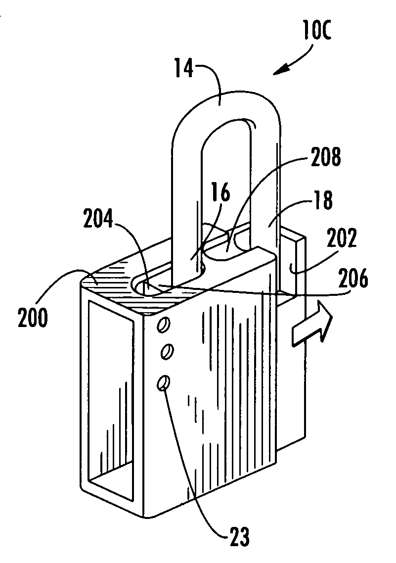
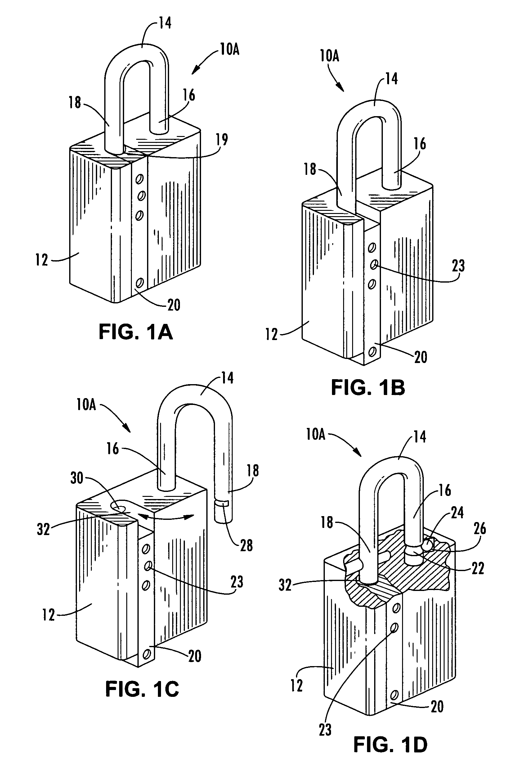
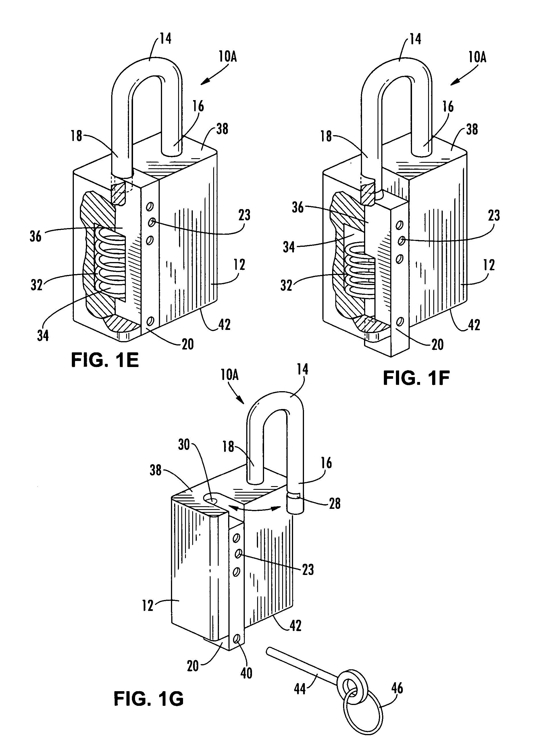
[0050]In the following are described the preferred embodiments of the multiple function lock in accordance with the present invention. In describing the embodiments illustrated in the drawings, specific terminology will be used for the sake of clarity. However, the invention is not intended to be limited to the specific terms so selected, and it is to be understood that each specific term includes all technical equivalents that operate in a similar manner to accomplish a similar purpose. Where like elements have been depicted in multiple embodiments, identical reference numerals have been used in the multiple embodiments for ease of understanding.

[0051]It will become evident to one skilled in the art that several objectives and advantages of this invention follow from the novel method by which the traditional security functions are achieved using tool operated restricting components to secure conventional engaging elements.

[0052]In conventional padlock-style security locks, the key ...


PUM


Abstract

A lock having a body, an engaging element having a first end, a locking mechanism for securing the first end to the body, the locking mechanism adapted to selectively conceal or reveal a passage in the body, through translation of a sliding gate, through which the first end may move to unlock the lock; the engaging element has a second end which is retained by the body at all times but is free to rotate. In other aspects, a lock has a body, a shackle having heel and toe portions, the heel portion engaged within the body, and a gate mechanism for selectively concealing or revealing a passage in the body from which the toe portion may move to unlock the lock, wherein movement of the toe portion is achieved through rotation of the toe about the heel.

Description

CROSS REFERENCE TO RELATED APPLICATIONS[0001]The present application is a continuation-in-part of U.S. patent application Ser. No. 10 / 871,800 filed Jun. 18, 2004, which is a continuation-in-part of U.S. patent application Ser. No. 10 / 845,624 filed May 13, 2004, which claims the benefit of the filings dates of U.S. Provisional Patent Application Ser. Nos. 60 / 470,999 filed May 16, 2003; 60 / 479,742 filed Jun. 19, 2003; 60 / 482,853 filed Jun. 26, 2003; and 60 / 512,615 filed Oct. 20, 2003. The present invention also claims the benefit of the filing date of U.S. Provisional Patent Application No. 60 / 590,201 filed Jul. 22, 2004. The disclosures of each of the aforementioned applications are hereby incorporated herein by reference.BACKGROUND OF THE INVENTION[0002]Conventional locks, such as padlocks employing U-shaped shackles, are extremely popular. One reason for their popularity is the ease and convenience of their attachment to, and fit with, the hasps and other attachment mechanisms of d...

Claims


Application Information

Patent Timeline
Patent Type & Authority Patents(United States)
IPC IPC(8): E05B67/38E05BE05B67/06
CPCE05B67/38E05B35/008E05B39/00E05B67/02E05B63/143E05B2015/0482E05B17/14Y10T70/489Y10T70/7147Y10T70/424Y10T70/498
Inventor LOUGHLIN, ROBERTLOUGHLIN, JOHN
Owner STANTON CONCEPTS
Why Eureka
Try Eureka