Conveyor roller with brake

a technology of conveyor rollers and brakes, applied in the field of conveyors, can solve the problems of excessive strain and wear on the drive gears and/or motors of the driving rollers, and achieve the effect of reducing the number of rollers

Inactive Publication Date: 2006-04-04
DEMATIC
View PDF19 Cites 46 Cited by
  • Summary
  • Abstract
  • Description
  • Claims
  • Application Information

AI Technical Summary

Benefits of technology

[0011]Therefore, the present invention provides a brake or braking device or brake cartridge for a roller of a conveyor. The braking device may be positioned at least partially within a roller portion of a roller and is selectively operable to stop or limit or restrict rotation of the roller portion of the roller relative to the axle portion of the roller. The braking device may be operable to allow substantially unrestricted rotation when a motorized roller is activated and to substantially restrict rotation when the motorized roller is deactivated. The braking device thus may stop rotation of the roller portion when the conveyor or zone or section is not conveying articles therealong. The braking device of the present invention may be implemented at an inclined conveyor section and may limit or substantially preclude the articles from moving down the inclined conveyor section when the motorized or driven roller is deactivated or stopped. The braking device functions to stop and hold the articles on the conveying surface, such that the motor and gears of the motorized roller do not have to perform such functions.

Problems solved by technology

Also, when such conveyors are arranged at an incline, the articles on the conveyor may tend to move back down the incline after the driving roller is stopped.
The stopping and / or reversing of the rollers of the conveyor may tend to cause excessive strain and wear on the drive gears and / or motor of the driving roller.

Method used


Image

  • Conveyor roller with brake
  • Conveyor roller with brake
  • Conveyor roller with brake

Examples


Embodiment Construction

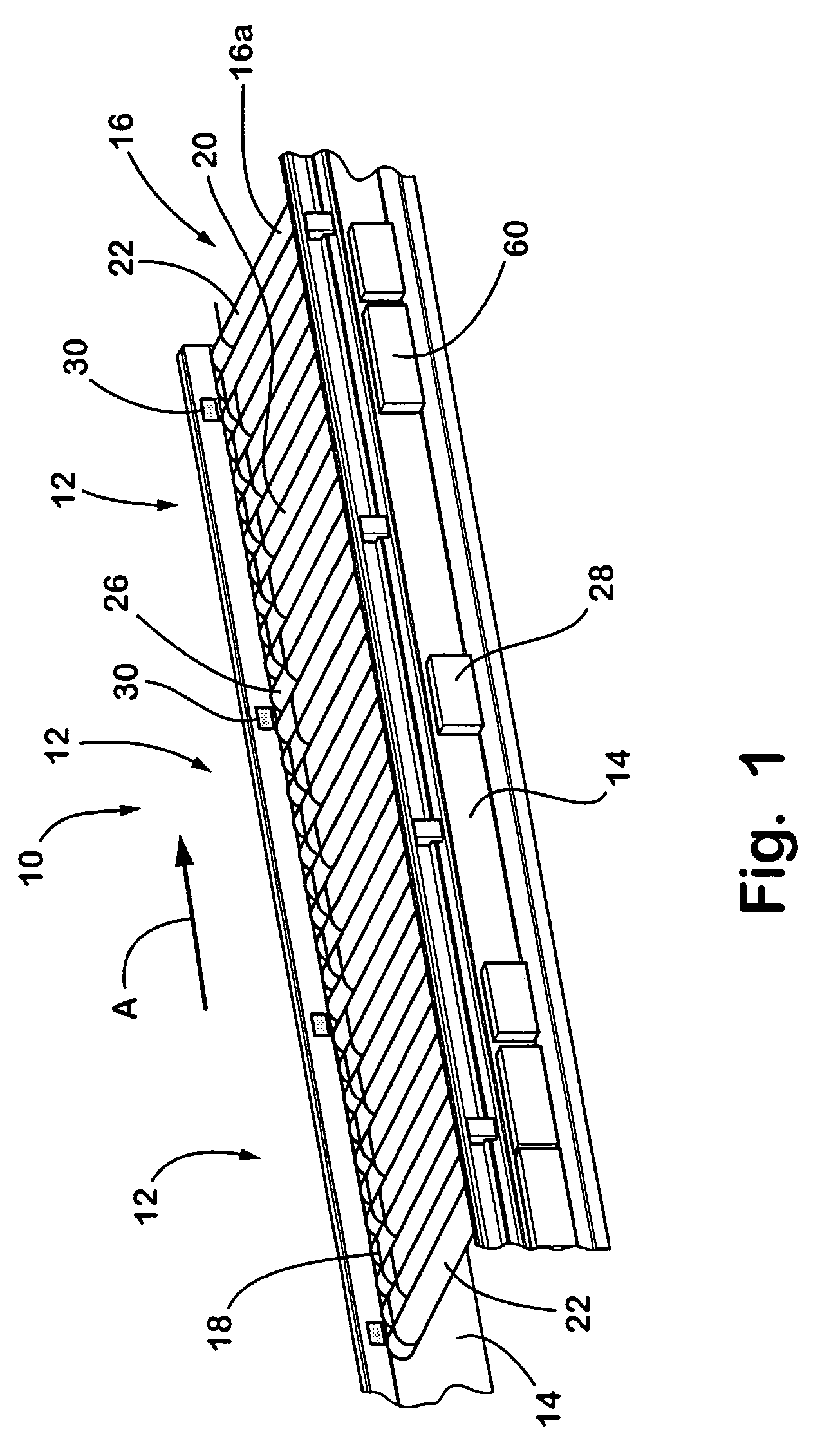
[0046]Referring now specifically to the drawings and the illustrative embodiments depicted therein, a roller conveyor 10 includes one or more zones or segments 12 positioned along and between opposite sidewalls or side frames 14, and is operable to convey articles in a direction of conveyance A (FIG. 1). Each segment or zone 12 includes a plurality of rollers 16 and a plurality of drive members 18 (such as O-rings or the like) around adjacent pairs of rollers 16. Each zone 12 may be independently operable to accumulate articles on the segment or zone or to move articles in the direction A onto a next, adjacent segment or zone or onto another conveyor, such as another roller conveyor, a belt conveyor, a slider bed, or the like, or any other means for receiving articles from a discharge end of the last zone or segment of roller conveyor 10.

[0047]Rollers 16 of each zone 12 include a motorized roller 20 and one or more non-motorized or idler rollers 22. Motorized roller 20 may rotatably...


PUM


Abstract

A conveyor roller or pulley includes an axle portion mountable to opposite sidewalls of a conveyor and a roller portion rotatable relative to said axle portion. The roller includes a braking device positioned at least partially within said roller portion and selectively operable to restrict rotation of said roller portion relative to said axle portion. The braking device may be biased to restrict rotation, such that the braking device restricts rotation when an actuator of the braking device is deactivated, and allows substantially unrestricted rotation when the actuator is activated. The actuator may be activated when a drive motor of the conveyor is activated to drive one of the rollers of the conveyor, and may be deactivated when the drive motor is deactivated. The conveyor may comprise a roller conveyor or a belted conveyor.

Description

CROSS REFERENCE TO RELATED APPLICATION[0001]The present application claims benefit of U.S. provisional application, Ser. No. 60 / 527,485, filed Dec. 5, 2003, which is hereby incorporated herein by reference in its entirety.FIELD OF THE INVENTION[0002]The present invention relates generally to conveyors and, more particularly, to conveyors having driven rollers or pulleys and idler rollers or pulleys, such as belt conveyors or roller conveyors.BACKGROUND OF THE INVENTION[0003]A belt or roller conveyor typically includes a driving roller or pulley and one or more idler rollers arranged along and between opposite sidewalls. The driving roller or pulley is operable to rotatably drive the other rollers, such as via a continuous conveyor belt reeved around the rollers or pulleys or such as via O-rings or the like around adjacent rollers. When the driving roller is activated, the rollers function to convey articles along the conveyor. When the driving roller is deactivated, the rollers may ...

Claims


Application Information

Patent Timeline
Patent Type & Authority Patents(United States)
IPC IPC(8): B65G13/06B65G13/075
CPCB65G13/075
Inventor HAAN, TED W.KOOISTRA, KENNETH J.
Owner DEMATIC
Why Eureka
Try Eureka