Automatic document feeding apparatus

Inactive Publication Date: 2006-04-04
NISCA KK
View PDF16 Cites 20 Cited by
  • Summary
  • Abstract
  • Description
  • Claims
  • Application Information

AI Technical Summary

Benefits of technology

[0014]With the configuration, it is possible to apply an appropriate pressing force and transport force to the original to prevent unsteady transportation without a complicated configuration. It is also possible to obtain stable reading of the image without scratching the film member. The platen roller is supported at a predetermined position above the platen.
[0015]According to the invention, the platen roller is arranged at a position away from the reading position of the reading unit. Specifically, in a direction that the platen roller transports the original, the platen roller is disposed at a position upstream of the reading position of the reading unit for pressing the original upstream of the reading position. Accordingly, when a trailing edge of the original exits from the transport means that transports the original toward the platen roller, the original is transported in a steady manner at the reading position. Further, even if the guide is scratched due to friction between the platen roller and guide means, the scratches occur at a position away from the reading position, thereby eliminating effect of the scratches on the reading of the original.
[0016]According to the present invention, the apparatus may be provided with the first transport means for transporting the original to the reading position of the reading unit and the second transport means for discharging the

Problems solved by technology

As a result, the original tends to vibrate or be transported at a various speed at the reading position, thereby causing distortion of the read image.
Further, when a trailing edge of the original passes through and exits a nipping point of the feed rollers 102, the trailing edge of the original drops downward to cause an unsteady transport of the original and a variation in the speed o

Method used


Image

  • Automatic document feeding apparatus
  • Automatic document feeding apparatus
  • Automatic document feeding apparatus

Examples


Embodiment Construction

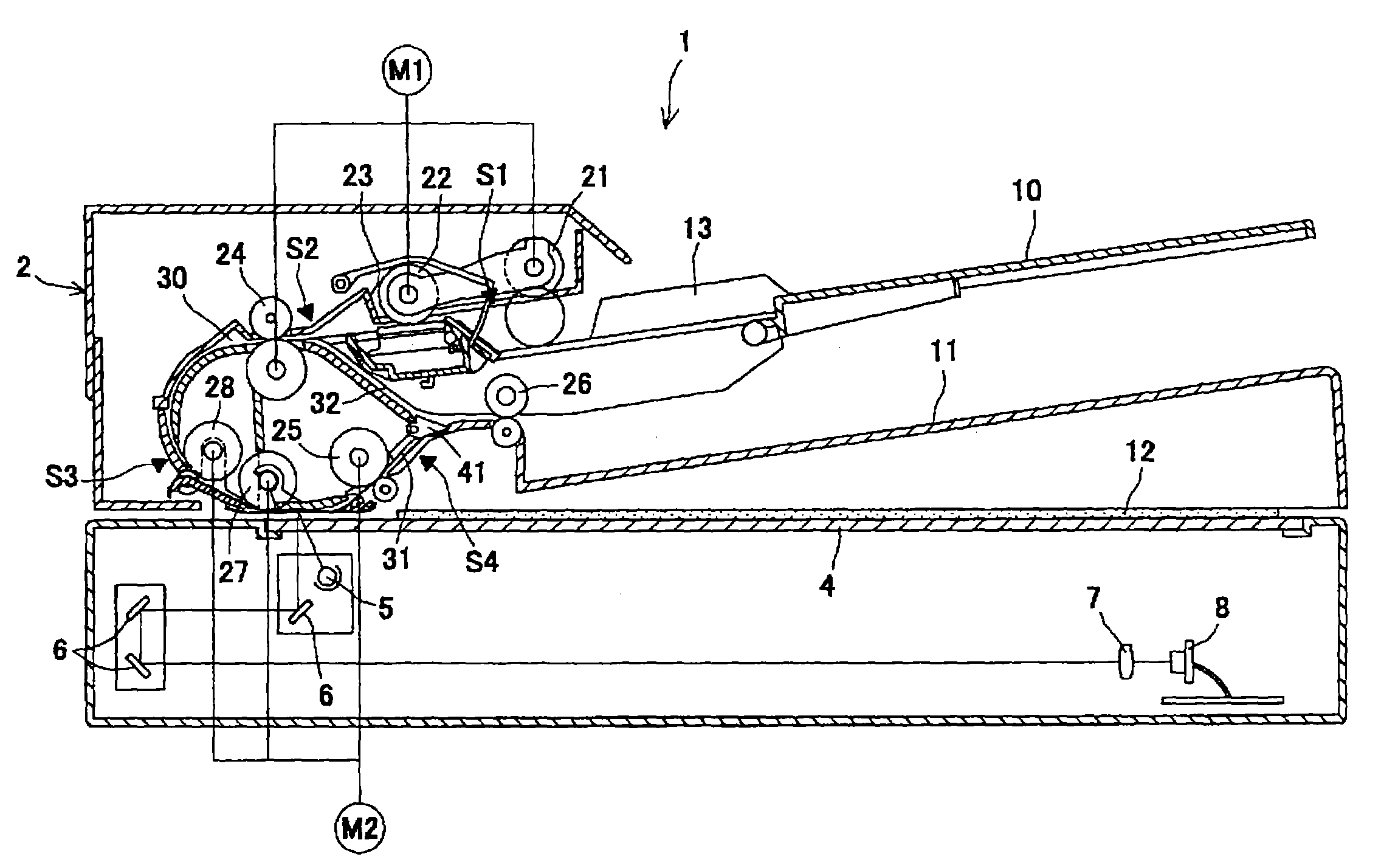
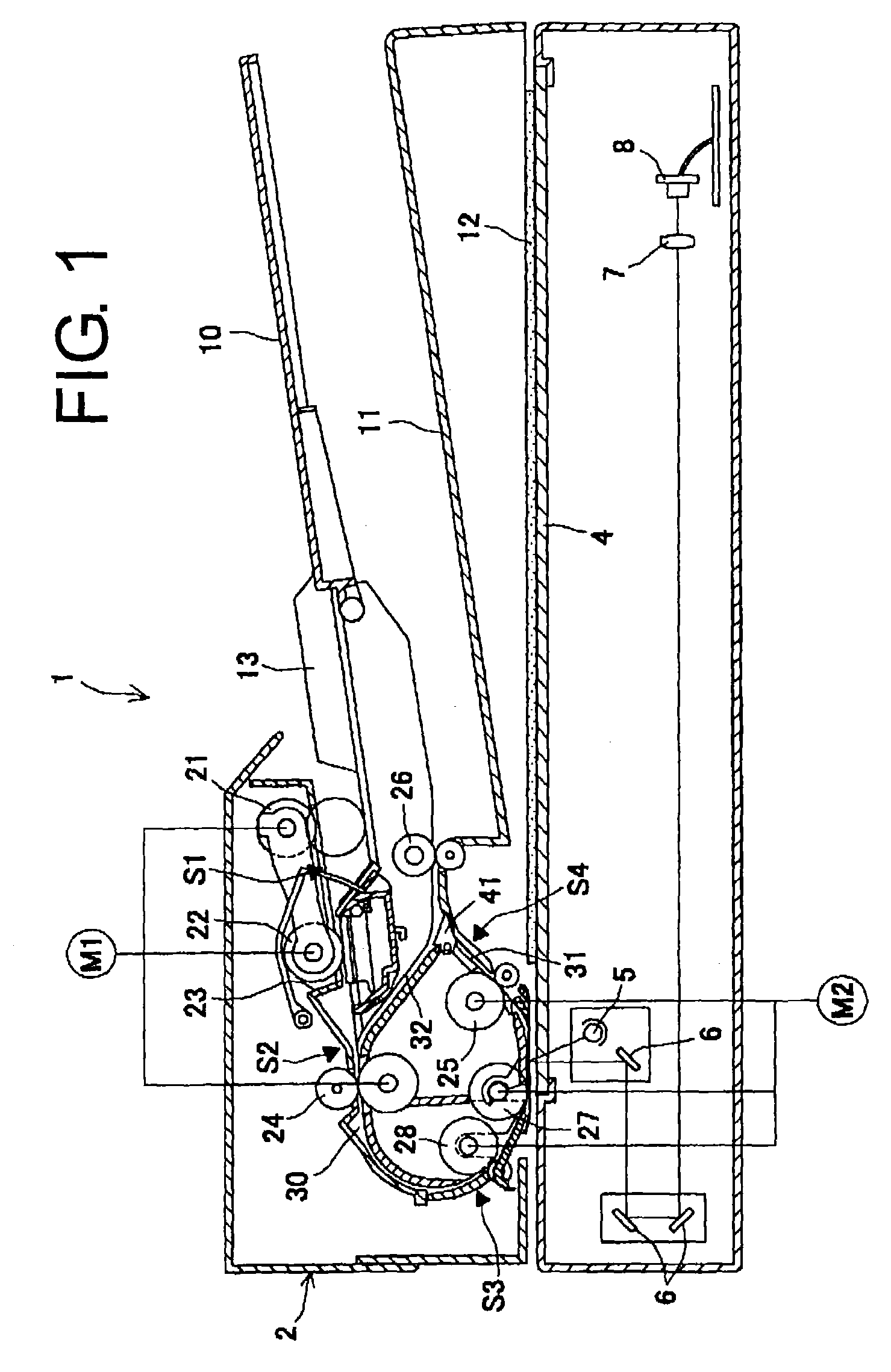
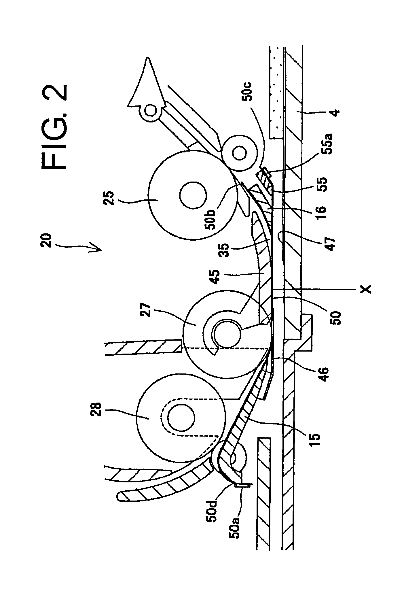
[0026]Hereunder, embodiments of the invention will be described with reference to the accompanying drawings. FIG. 1 is a view showing an automatic document feeder 2 mounted on an original reading apparatus 1 according to the present invention. FIG. 2 is a view showing a main portion of the automatic document feeder 2.

[0027]In a main unit of the original reading apparatus 1, a light source 5 such as a lamp radiates light onto a transported original through a platen 4. A plurality of mirrors 6 reflects the light from the original into a reading element 8 such as a CCD via a lens 7 to read an image on the original and convert photo-electrically. The original reading apparatus 1 has a mode in which an optical unit having the light source 5 and mirrors 6 moves in a sub-scanning direction to read an image on a thick original placed on a platen 4 through the platen 4, and a mode in which a stationary optical unit reads an original transported over the platen 4 by the automatic document fee...


PUM


Abstract

An automatic document feeder is provided with a reading unit disposed above a platen for reading an original. The reading unit includes a platen roller for transporting the original to the reading unit; a guide device arranged between the platen and the platen roller and formed in a curved original reading path; a pressing device for pressing the guide device against the platen roller; and a regulating device for creating a space between a surface of the platen roller and an upper surface of the platen. When the original is transported between the platen roller and the guide device, the original moves the guide device toward the platen.

Description

BACKGROUND OF THE INVENTION AND RELATED ART STATEMENT[0001]The present invention relates to an original reading apparatus provided in an image forming apparatus such as a copier or facsimile, and particularly to an automatic document feeding apparatus or feeder in an original reading apparatus.[0002]In an optical reading apparatus provided in an image forming apparatus, methods of reading an original include a stationary original reading method in which transport means such as a belt or roller feeds an original on a platen, and an optical reading system scans the original placed stationary on the platen to read an image on the original, and a sheet through reading method in which an optical reading system situated at a fixed reading position reads an original while a feeding apparatus is transporting the original.[0003]In the sheet through reading method, a conventional original reading apparatus includes the first platen for placing the original and the second platen arranged adjac...

Claims


Application Information

Patent Timeline
IPC IPC(8): B65H5/00B65H5/36G03B27/50G03G15/00H04N1/00H04N1/04
CPCG03G15/60
Inventor WATANABE, YASUHITOAOYAGI, TATSUZOENDO, FUMIHITO
Owner NISCA KK
Why Eureka
Try Eureka