Eureka AIR delivers breakthrough ideas for toughest innovation challenges, trusted by R&D personnel around the world.

Rollable baffled ridge vent

a ridge vent and baffle technology, applied in the field of attic ventilation, can solve the problems of exceedingly inefficient attic ventilation, less sophisticated design and configuration, and difficult installation, and achieve the effect of reducing the nfa of the vent, not degrading the air flow through the vent, and providing for rollability of the ven

Inactive Publication Date: 2006-04-11
HBP ACQUISITION
View PDF36 Cites 34 Cited by
  • Summary
  • Abstract
  • Description
  • Claims
  • Application Information

AI Technical Summary

Benefits of technology

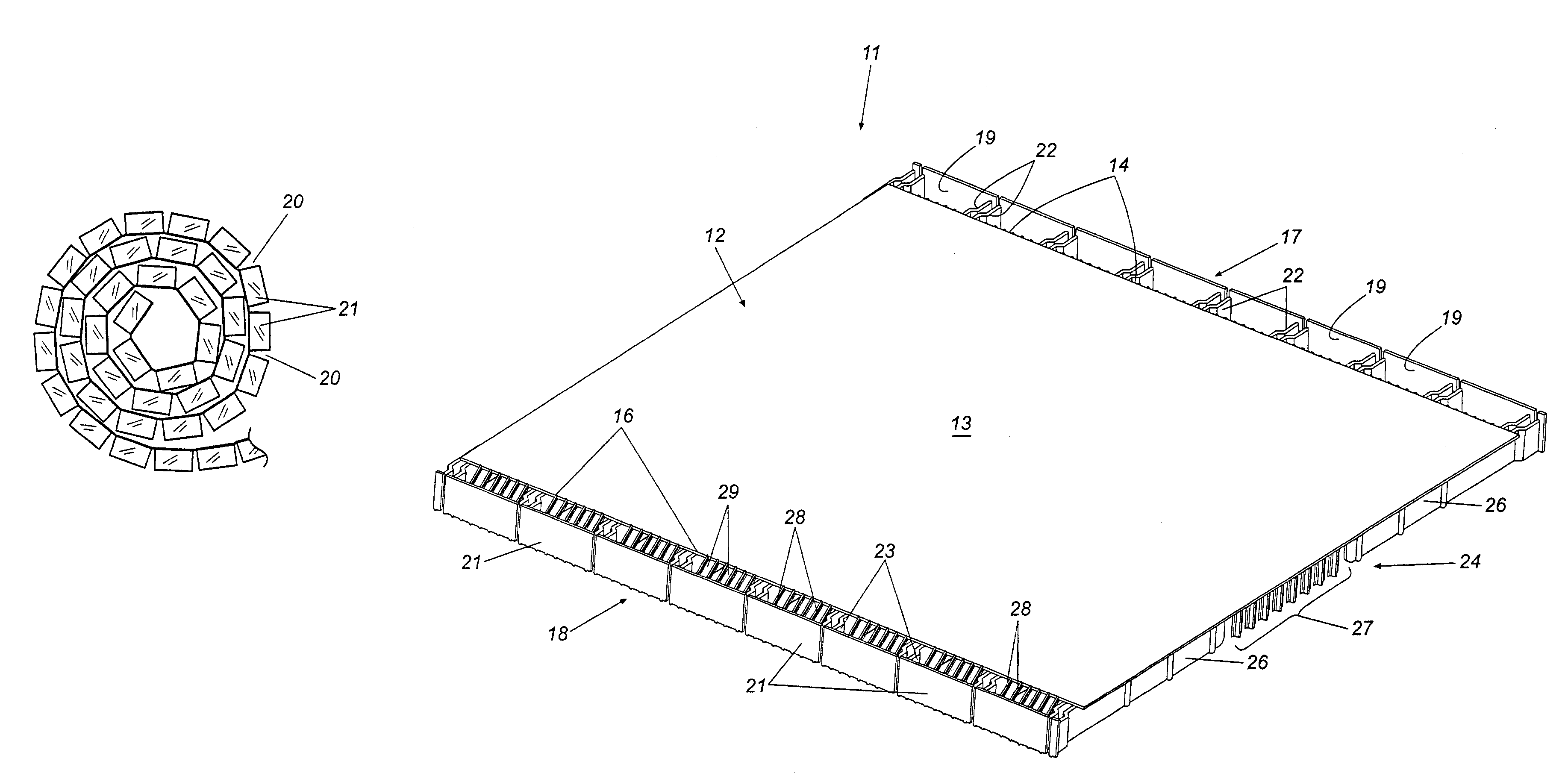
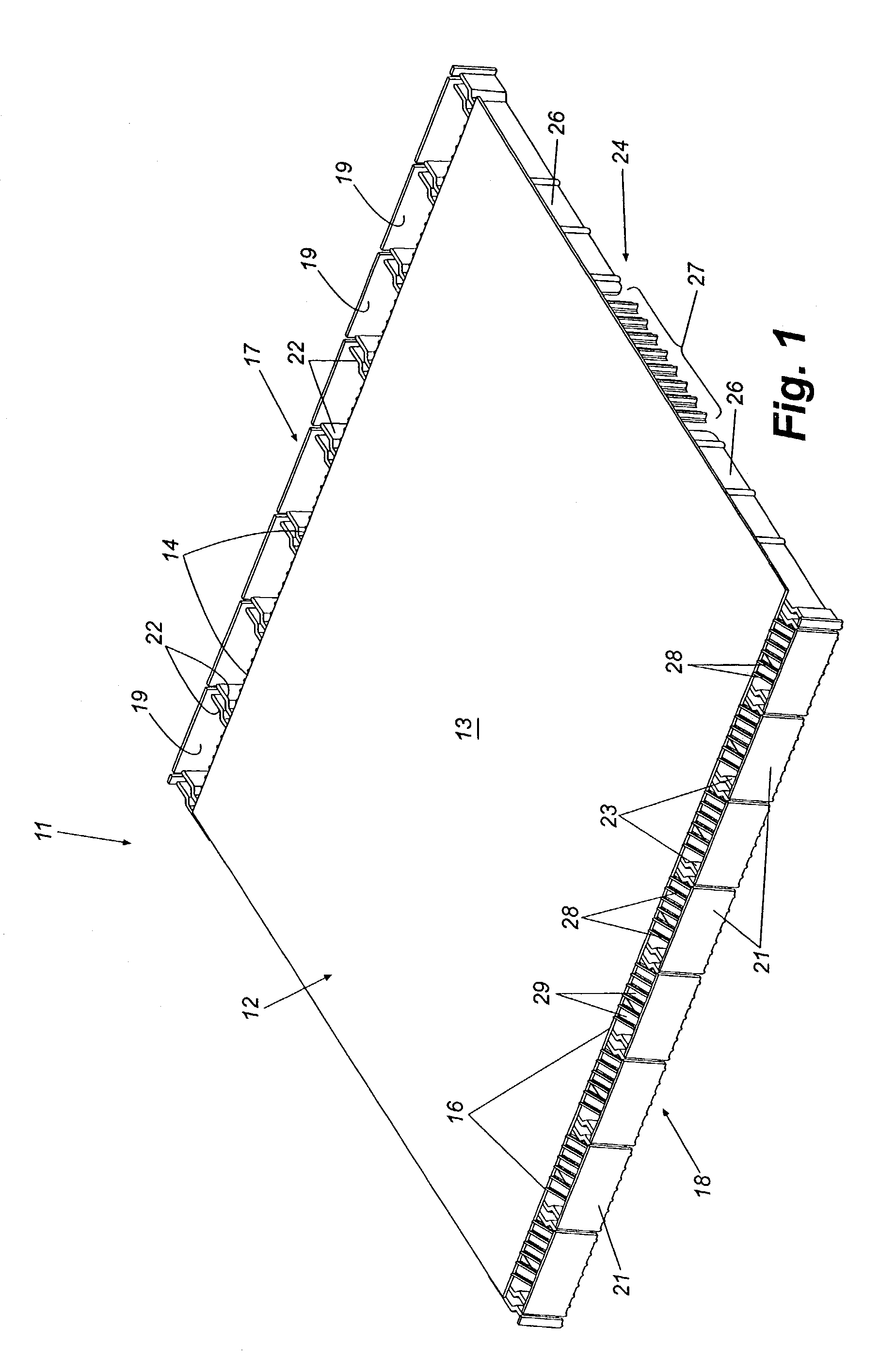
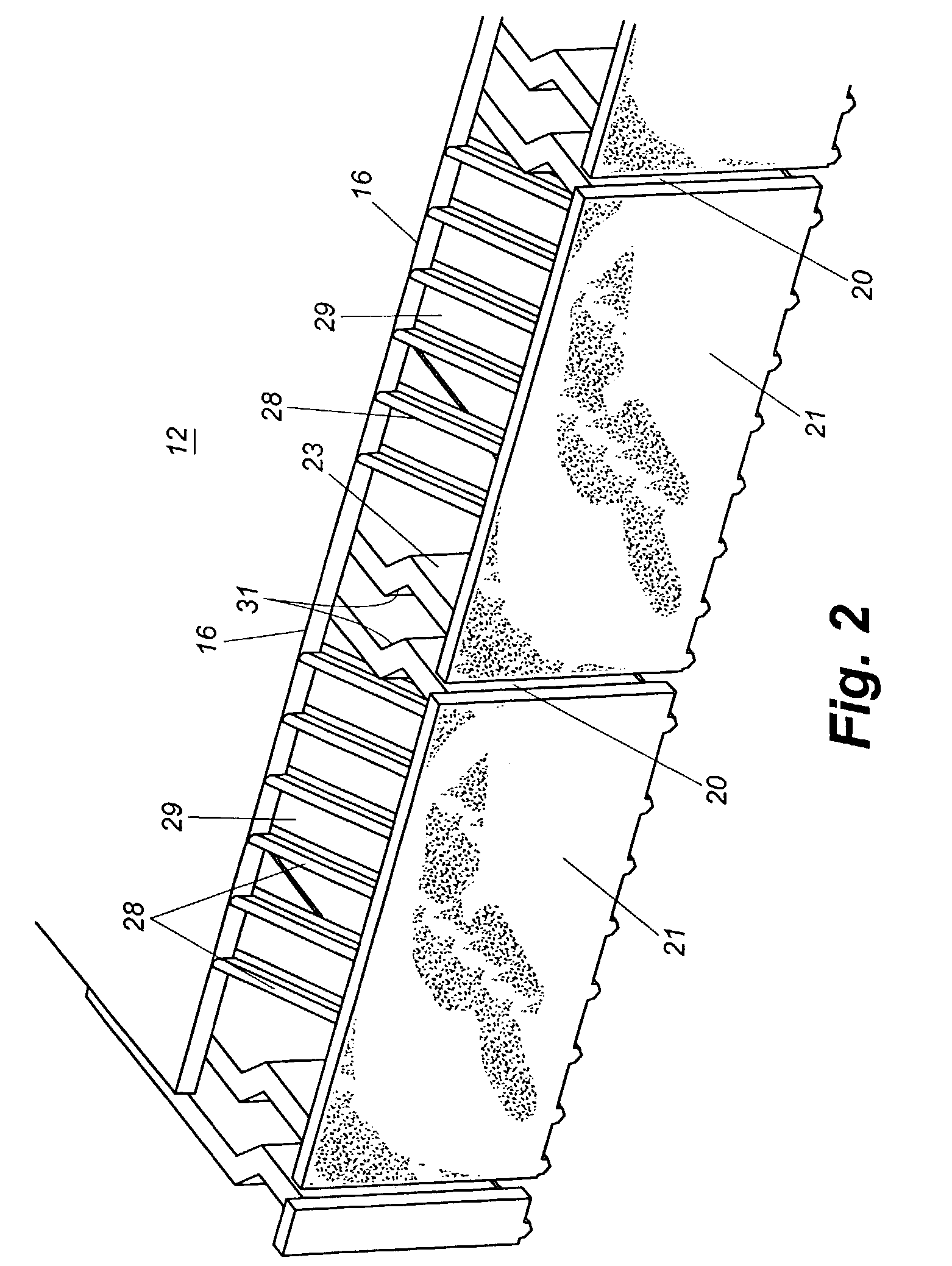
[0008]In order to provide for rollability of the vent, the flat upstanding outboard wind baffle is defined by a series of relatively short baffle sections that each is supported by a pair of buttresses extending laterally from beneath the panel. The buttresses project a significant distance inwardly toward the center portion of the panel such that, in addition to supporting the baffle sections, they also form a series of laterally extending supports on the underside of the panel. These supports rest on the roof and maintain spacing between the roof shingles and the underside of the panel to provide a plenum through which air flows laterally out the side vents. Since the supports are relatively thin and extend in a lateral direction relative to the panel, they do not significantly reduce the NFA of the vent and thus do not degrade the air flow through the vent.
[0009]The sectioned flat baffle sections are aligned and co-extensive and together form a substantially continuous outboard flat wind baffle similar to those of panel-type ridge vents. This configuration preserves the laminar flow of wind across the vent and the resulting low pressure in the region of the louvered opening that enhances air flow. However, when the vent is rolled up along its length, the adjacent baffle sections splay with respect to each other. This allows long sections of vent to be delivered in rolls and rolled out along a roof ridge for installation similar to traditional open weave mat-type vents. The spacing between the ribs of the louvered vent, the space between the edges of the panel and the baffle, and the thickness of the laterally extending supports are selected to provide the maximum possible NFA. All of these features provide ventilating performance similar to that of traditional panel-type ridge vents. Further, the flat design of the baffles and the simple lateral supports / baffle buttresses require a minimum of plastic material during fabrication.

Problems solved by technology

The failure to provide adequate ventilation can result in a variety of serious problems including, for example, the growth of mold in and around the attic space.
However, they are difficult and time consuming to install because each panel must be installed separately in end-to-end relationship with adjacent panels.
However, since rolled ridge vents must be flexible in order to be rolled, they typically are much less sophisticated in design and configuration that panel-type ridge vents and sometimes are nothing more that long bats of loosely woven fibrous plastic material that presumably allow air flow to flow through their open weave structure.
As a result, rolled ridge vents, although easy to install, have been shown to be exceedingly inefficient at providing attic ventilation and some are not much better than having no vent at all.
While the design of this ridge vent may be a step in the right direction, it nevertheless has its own set of problems and shortcomings.
For example, the corrugated or “undulating” configuration of the wind baffles increases substantially the amount of plastic required to mold the panel and thus increases the cost of the product.
More importantly, the support structures and vent design of this product decreases its net-free-area (NFA) and therefore decreases its ventilation efficiency.
Accordingly, although the product disclosed in the '315 patent purportedly is rollable, it still fails to provide the corresponding high efficiency ventilation of well designed panel-type ridge vent systems.

Method used


Image

  • Rollable baffled ridge vent
  • Rollable baffled ridge vent
  • Rollable baffled ridge vent

Examples


Embodiment Construction

[0017]Referring now in more detail to the drawings, in which like reference numerals refer to like parts throughout the several views, FIG. 1 illustrates a relatively short section of a rollable baffled ridge vent that embodies principles of the present invention in a preferred form. It will be understood that a complete ridge vent is much longer than the short section illustrated in FIG. 1 for unrolling from a rolled-up configuration along the ridge of a roof. A short section is illustrated in the drawings for simplicity and clarity of description. The ridge vent 11, which is made of molded plastic, is formed with a top panel 12 having a laterally flexible central portion 13 and edges 14 and 16. Wind baffles 17 and 18 extend along and outboard of respective edges 14 and 16. Wind baffle 17 is defined by a plurality of aligned coextensive rectangular baffle sections 19 that together form a wind baffle that presents a generally flat face to a lateral wind blowing across the ridge vent...


PUM


Abstract

A rollable baffled ridge vent has a top panel with a laterally flexible central portion and edges. Substantially flat wind baffles are supported outboard of the edges and each wind baffle is formed by an array of aligned coextensive rectangular baffle sections. Each baffle section is supported by a pair of buttresses that project from beneath the top panel. Some of the buttresses also extend inwardly toward the central portion of the panel to form supports for supporting the ridge vent on a roof. The ridge vent can be fabricated in roof length sections that can be rolled into rolls with the baffle sections splaying with respect to each other to provide rollability. For installation, the ridge vent is rolled out along the open ridge of a roof and attached with nails. Superior ventilation is provided by the high net free area and flat wind baffle design of the vent while preserving the convenience of a rollable product.

Description

TECHNICAL FIELD[0001]This invention relates generally to attic ventilation and more specifically to “shingle-over” ridge vents installable along an open ridge of a roof to provide ventilation.BACKGROUND[0002]It is important when constructing modern homes and other buildings that the attic space of the building be adequately ventilated. The failure to provide adequate ventilation can result in a variety of serious problems including, for example, the growth of mold in and around the attic space. A variety of attic ventilation techniques and products have been used over the years to provide attic ventilation. These include open-eve vents, attic fans, and convection vents spaced along a roof near its ridge. More recently, so called “shingle-over ridge vents” have become increasingly ubiquitous in homes and commercial buildings. A shingle-over ridge vent is a long usually plastic panel that generally is installed along the ridge of a roof covering an open slot formed therealong. The rid...

Claims


Application Information

Patent Timeline
Patent Type & Authority Patents(United States)
IPC IPC(8): E04H12/28E04D13/17
CPCE04D13/176
Inventor HEADRICK, J. CHARLES
Owner HBP ACQUISITION
Why Eureka
Eureka Blog
Learn More