Manually separable ridge vent

a ridge vent and man-made technology, applied in the field of attic ventilation, can solve the problems of exceedingly inefficient attic ventilation, difficult installation and time-consuming, and are typically less sophisticated in design and configuration than panel-type ridge vents, and achieves superior ventilation and air flow. superior, easy-to-install

Inactive Publication Date: 2007-01-23
HBP ACQUISITION
View PDF41 Cites 37 Cited by
  • Summary
  • Abstract
  • Description
  • Claims
  • Application Information

AI Technical Summary

Benefits of technology

[0011]In order to provide for rollability of the vent, the substantially flat upstanding outboard wind baffle is defined by a series of relatively short baffle sections that each is supported by a pair of buttresses extending laterally from beneath the panel. The buttresses project a significant distance inwardly toward the center portion of the panel such that, in addition to supporting the baffle sections, they also form a series of laterally extending supports on the underside of the panel. These supports rest on the roof and maintain spacing between the roof shingles and the underside of the panel to provide a plenum through which air flows laterally out the side vents. Since the supports are relatively thin and extend in a lateral direction relative to the panel, they do not significantly reduce the NFA of the vent and thus do not degrade the air flow through the vent.
[0012]The sectioned substantially flat baffle sections are aligned and co-extensive and together form a substantially continuous outboard substantially flat wind baffle similar to those of panel-type ridge vents. This configuration preserves the laminar flow of wind across the vent and the resulting low pressure in the region of the louvered opening, which enhances air flow. However, when the vent is rolled up along its length, the adjacent baffle sections splay with respect to each other. This allows long sections of vent to be delivered in rolls and rolled out along a roof ridge for installation similar to traditional open weave mat-type vents. The spacing between the ribs of the louvered vent, the space between the edges of the panel and the baffle, and the thickness of the laterally extending supports are selected to provide the maximum possible NFA. All of these features provide ventilating performance similar to that of traditional panel-type ridge vents. Further, the flat design of the baffles and the simple lateral supports / baffle buttresses require a minimum of plastic material during fabrication.
[0014]In use, an installer installs ridge vent of this embodiment along the ridge of a roof in the usual way. When the end of the roof ridge is reached, a tear line that is near where the vent should terminate is selected and the vent is separated simply be being manually torn along the tear line. The resulting end is then attached to the roof with nails or staples with one of the depending partitions automatically forming an end wall or end plug that prevents leakage and infestation through the end of the ridge vent. Ridge shingles are then installed on top of the vent in the traditional way and installation is completed.
[0015]Accordingly, a rollable baffled ridge vent is now provided that addresses successfully the problems and shortcomings of the prior art. Long sections of the vent may be rolled-up into convenient rolls and installed quickly and easily just like mat-type ridge vents. Nevertheless, the vent of this invention provides superior ventilation similar to traditional panel-type ridge vents. It exhibits maximum NFA for superior air flow and requires a minimum of plastic for its construction. The ridge vent also incorporates features allowing it to be manually torn or separated at the end of a roof ridge, thus eliminating the need for measuring, cutting, and plugging the ridge vent at its end. These and other features, objects, and advantages of the present invention will become more apparent upon review of the detailed description set forth below when taken in conjunction with the accompanying drawing figures, which are briefly described as follows.

Problems solved by technology

The failure to provide adequate ventilation can result in a variety of serious problems including, for example, the accumulation of moisture in and around the attic space and problems associated therewith.
However, they are difficult and time consuming to install because each panel must be installed separately in end-to-end relationship with adjacent panels.
However, since rolled ridge vents must be flexible in order to be rolled, they typically are much less sophisticated in design and configuration than panel-type ridge vents.
As a result, rolled ridge vents, although easy to install, have been shown to be exceedingly inefficient at providing attic ventilation and some are not much better than having no vent at all.
While the design of this ridge vent may be a step in the right direction, it nevertheless has its own set of problems and shortcomings.
For example, the corrugated or “undulating” configuration of the wind baffles increases substantially the amount of plastic required to mold the panel and thus increases the cost of the product.
More importantly, the support structures and vent design of this product decreases its net-free-area (NFA) and therefore decreases its ventilation efficiency.
Accordingly, although the product disclosed in the '315 patent purportedly is rollable, it still fails to provide the corresponding high efficiency ventilation of well designed panel-type ridge vent systems.
Another problem with rollable ridge vents, and, indeed, panel-type ridge vents as well, relates to the need to cut the vents near the end of a ridge along which they are being installed.
This process is time consuming, can be frustrating for the installer, and is subject to human error in measurement and cutting.
Cutting the end of a ridge vent also can result in a gap between the roof deck and the vent panel at the end of a length of ridge vent.
Such a gap is unacceptable because it provides an entry point for blowing rain, insects, and vermin to enter the attic.
This is even more time consuming and frustrating and can even be skipped by an installer, causing leakage and infestation problems.
Another problem when cutting some types of ridge vent is the resulting production of scrap pieces of vent.

Method used


Image

  • Manually separable ridge vent
  • Manually separable ridge vent
  • Manually separable ridge vent

Examples


Embodiment Construction

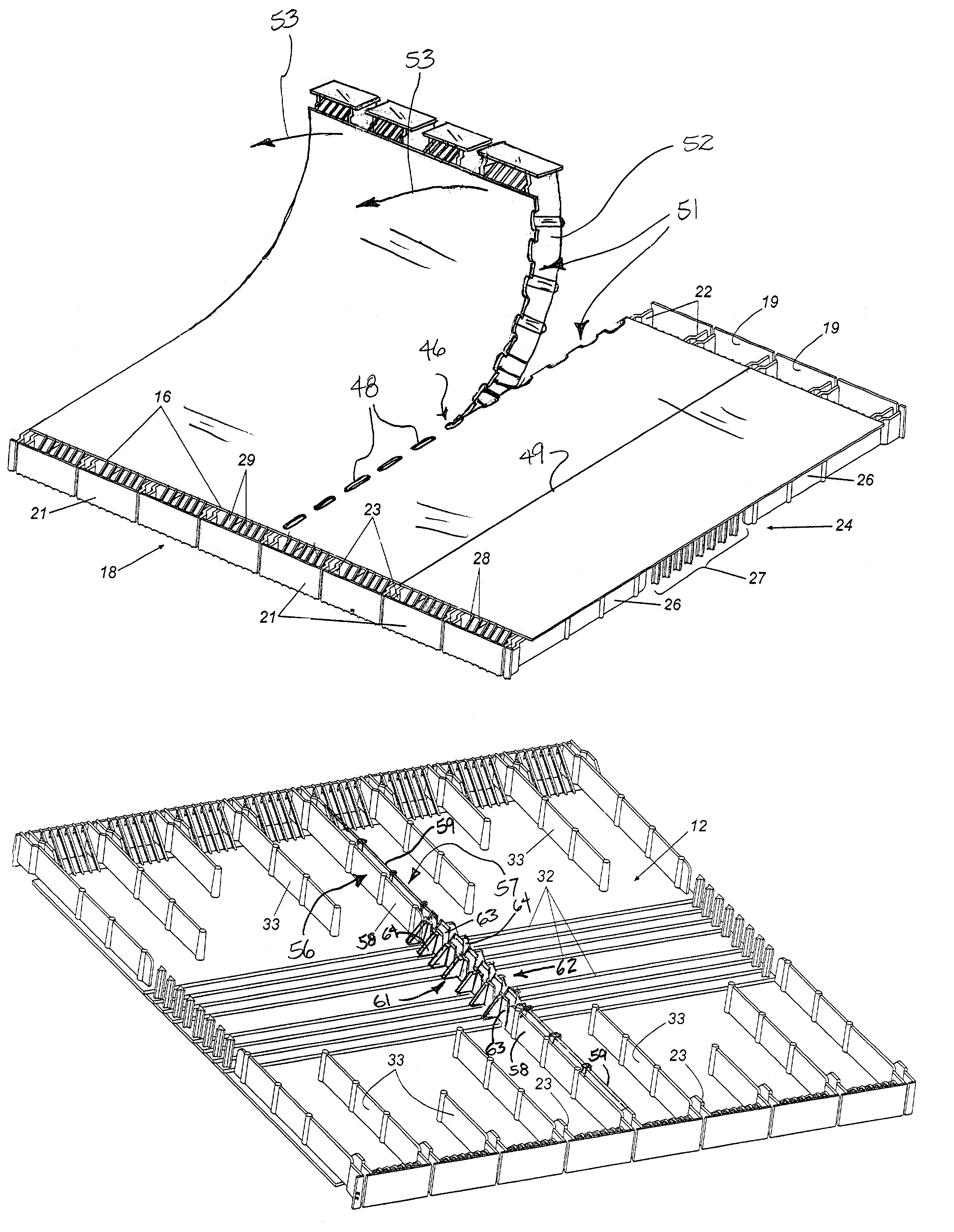
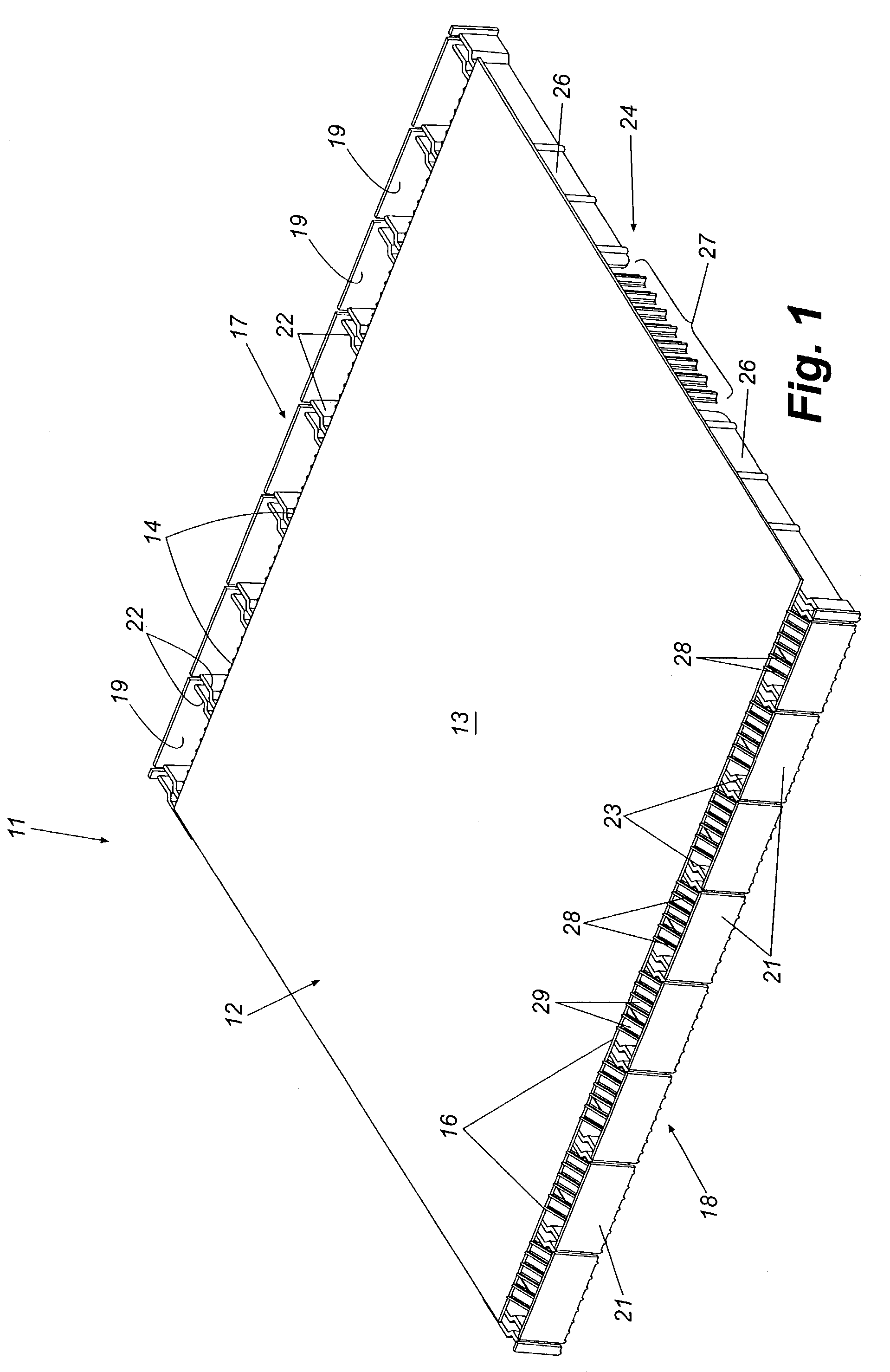
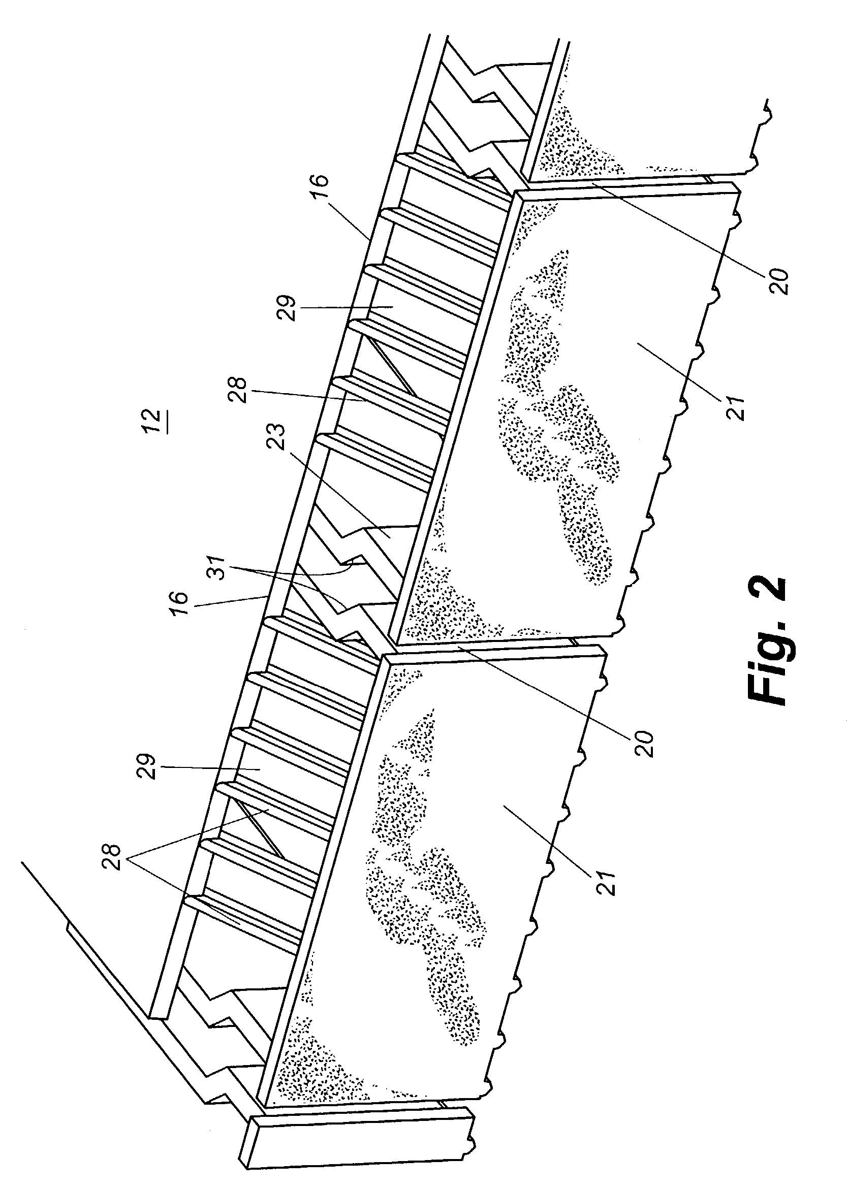
[0026]Referring now in more detail to the drawings, in which like reference numerals refer to like parts throughout the several views, FIG. 1 illustrates a relatively short section of a rollable baffled ridge vent that embodies principles of the present invention in a preferred form. It will be understood that a complete ridge vent is much longer than the short section illustrated in FIG. 1 for unrolling from a rolled-up configuration along the ridge of a roof. A short section is illustrated in the drawings for simplicity and clarity of description. The ridge vent 11, which is made of molded plastic, is formed with a top panel 12 having a laterally flexible central portion 13 and edges 14 and 16. Wind baffles 17 and 18 extend along and outboard of respective edges 14 and 16. Wind baffle 17 is defined by a plurality of aligned coextensive substantially rectangular baffle sections 19 that together form a wind baffle that presents a generally flat or smooth face to a lateral wind blowi...


PUM


Abstract

A ridge vent has an elongated body having a width sufficient to span the ridge of a roof along which the ridge vent is installed. Tear lines of relative weakness are formed at spaced intervals along the elongated body. The tear lines may be formed by score lines, perforations, or otherwise and are configured to allow the body of the ridge vent to be separated manually at a selected tear line by grasping the body and tearing along the tear line.Depending partitions may be disposed on the underside of the body on either side of each tear line to form end walls at new ends formed when the ridge vent is separated along a tear line.

Description

REFERENCE TO RELATED APPLICATION[0001]This is a continuation-in-part of U.S. patent application Ser. No. 10 / 293,376 filed Nov. 12, 2002 now U.S. Pat No. 7,024,828. My prior U.S. Pat. Nos. 6,227,963 and 6,371,847 are hereby incorporated by reference as if fully set forth herein.TECHNICAL FIELD[0002]This invention relates generally to attic ventilation and more specifically to “shingle-over” ridge vents installable along an open ridge of a roof to provide ventilation.BACKGROUND[0003]It is important when constructing modern homes and other buildings that the attic space of the building be adequately ventilated. The failure to provide adequate ventilation can result in a variety of serious problems including, for example, the accumulation of moisture in and around the attic space and problems associated therewith. A variety of attic ventilation techniques and products have been used over the years to provide attic ventilation. These include open-eve vents, attic fans, and convection ven...

Claims


Application Information

Patent Timeline
Patent Type & Authority Patents(United States)
IPC IPC(8): E04B7/00E04D13/17
CPCE04D13/176
Inventor HEADRICK, II, JOHN C.HEADRICK, J. CHARLES
Owner HBP ACQUISITION
Why Eureka
Try Eureka