
Tracking telescoping outrigger

a telescoping outrigger and tracking technology, applied in fishing, special-purpose vessels, vessel construction, etc., can solve the problems of lack of interspersed guide sleeves between the telescoping tubes, lack of ready means for cleaning and/or repair, and lack of a sure means to align the internal mounted buttons, etc., to prevent substantial relative rotation and facilitate cleaning and repair

Inactive Publication Date: 2006-04-11
EASTERN METAL SUPPLY
View PDF6 Cites 38 Cited by
  • Summary
  • Abstract
  • Description
  • Claims
  • Application Information

AI Technical Summary

Benefits of technology

"The invention is an improved telescoping outrigger that can be easily disassembled for cleaning and repair. It includes a mechanism for keeping the spring in place and a way to track the telescoping sections so they don't rotate. The outrigger has multiple tubes that can extend and retract, and a sleeve with tracking means to keep them aligned. It also has locking means to keep the tubes in place. This design makes it easier to maintain and adjust the outrigger for different conditions."

Problems solved by technology

Thus, this device provides no ready means for disassemblement for cleaning and / or repairs.
Furthermore, this type of device does not provide a sure means to align the internally mounted button with the hole in the external tube to fix the tubes in the fully extended position.
Whatever this device's utility is with regard to umbrellas, it lacks an interspersed guide sleeve between the telescoping tubes.

Method used


Image

  • Tracking telescoping outrigger
  • Tracking telescoping outrigger
  • Tracking telescoping outrigger

Examples


Embodiment Construction

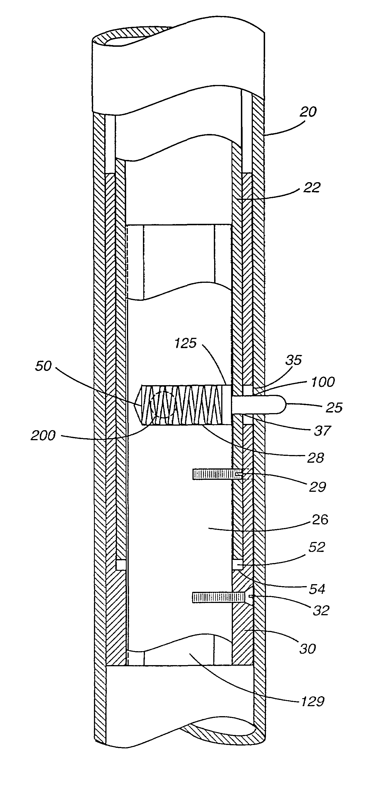
[0029]Referring to the Figures, a portion of an outrigger is shown in FIGS. 2 and 3 and comprises an outer tube 20 telescoping with an inner tube 22. Our invention provides a positive means for tracking the tubes as they are manipulated from the retracted to the extended position. This tracking means consists of a longitudinally extending protrusion running the length of an outer tube 20 and a longitudinally extending groove running the length of a mating sleeve 30. These parts are shown, for example, in FIGS. 2, 3 and 5, wherein the protrusion is illustrated at 70 and groove is shown at 72.

[0030]An additional longitudinally extending protrusion on the inner wall of the sleeve 30 is provided at 74, FIGS. 2 and 3, to mate with an additional groove 76, in the next juxtaposed tube 22. These protrusions are shown in line radially in FIG. 3. However, they need not be so aligned, as shown in FIG. 4 at 70 and 174. Each protrusion must be in line with its mating groove. The protrusions are ...


PUM


Abstract

An outrigger has a plurality of telescoping tubes capable of being retracted and extended with respect to one another, and a sleeve between the tubes; and the tubes and sleeve having longitudinal tracking comprising interlocking protrusions and grooves to permit the tubes to be retracted and extended, while preventing substantial relative rotation therebetween. There is a ring attached to the outer tube; by readily detachable screws.

Description

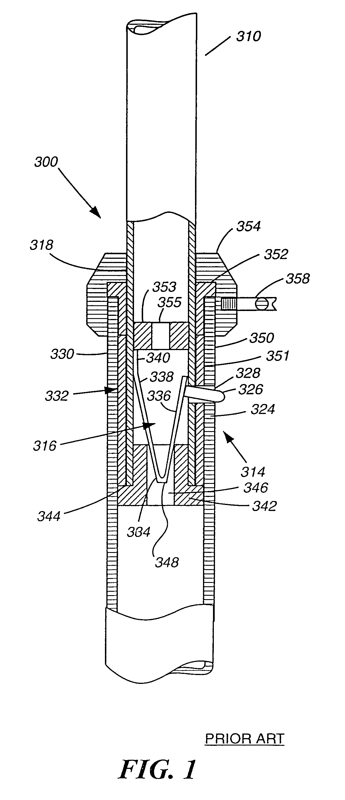
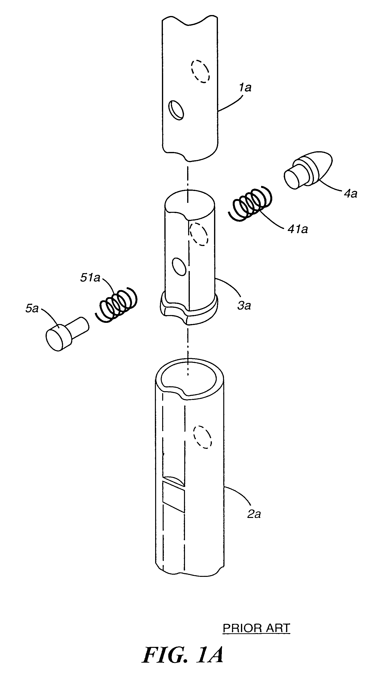
CROSS REFERENCE TO RELATED APPLICATIONS[0001]This application is a continuation-in-part of the filing date of our prior application Ser. No. 10 / 620,011 filed Jul. 15, 2003 now abandoned, and the provisional application No. 60 / 450,832, filed Feb. 28, 2003 and the provisional application No. 60 / 396,067 filed Jul. 15, 2002 which was referenced therein, the disclosures of all of which are incorporated herein by reference as if fully set forth.BACKGROUND OF THE INVENTION[0002]1. Technical Field[0003]This invention relates to fishing gear for use on a boat and, in particular, to a piece of equipment known as an outrigger for guiding trolling lines outwardly from the boat for luring fish.[0004]2. Description of the Prior Art[0005]In the prior art, sport fishing boats are typically equipped with outriggers for extending fishing and trolling lines out and beyond the wake of the moving boat and into calmer water where the fish are more apt to take the lure or bait. One such outrigger is shown...

Claims


Application Information

Patent Timeline
Patent Type & Authority Patents(United States)
IPC IPC(8): B63B35/14A01K91/08B63B17/00
CPCA01K91/08B63B35/14B63B17/00
Inventor WILCOX, ROGERWILCOX, SCOTT A.
Owner EASTERN METAL SUPPLY
Learn More