Multi-component drain and serving tray assembly

Inactive Publication Date: 2006-04-11
CHEN SHANE
View PDF9 Cites 37 Cited by
  • Summary
  • Abstract
  • Description
  • Claims
  • Application Information

AI Technical Summary

Problems solved by technology

While these and other devices make a contribution to the serving and drain tray art, they are disadvantageous for several reasons including that they are limited to a specific function.
The result is added expense in purchasing each of these different articles and added clutter in the kitchen.

Method used


Image

  • Multi-component drain and serving tray assembly
  • Multi-component drain and serving tray assembly
  • Multi-component drain and serving tray assembly

Examples


Embodiment Construction

taken together with the drawings.

BRIEF DESCRIPTION OF THE DRAWINGS

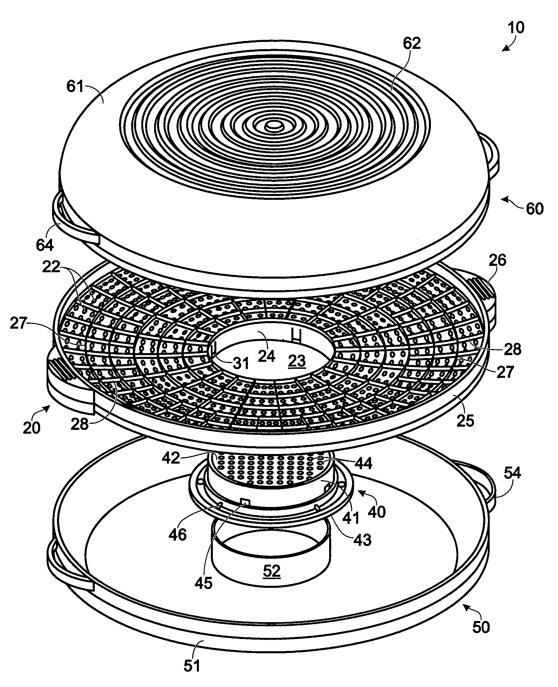
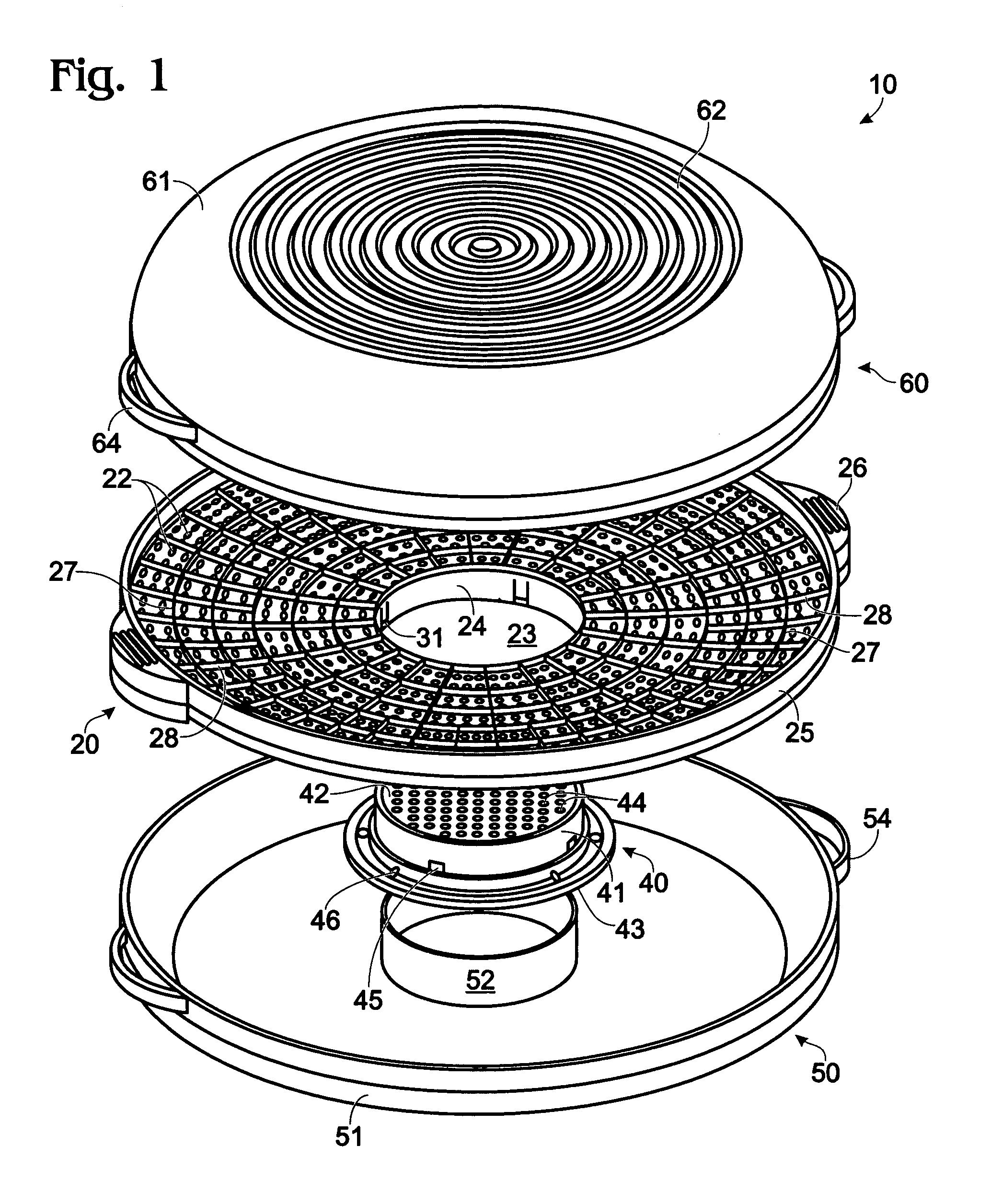
[0011]FIG. 1 is an exploded perspective view of one embodiment of a drain tray assembly in accordance with the present invention.

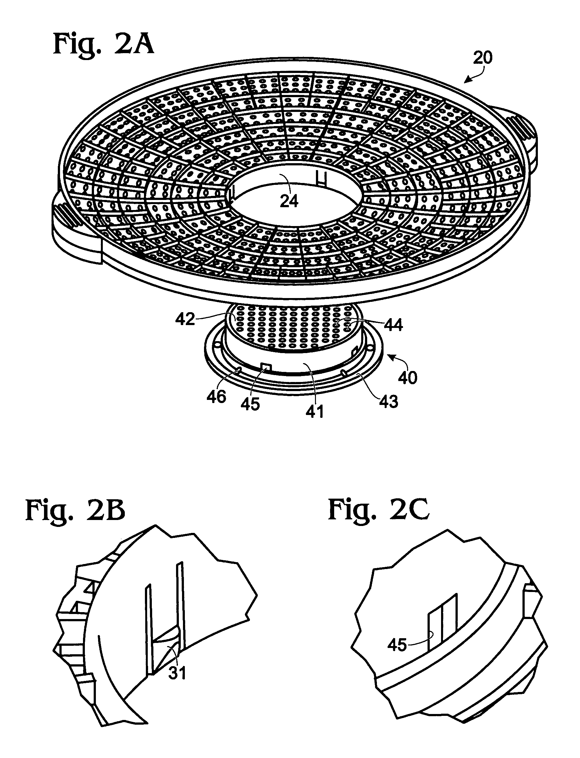
[0012]FIGS. 2A–2C are perspective views of a drain tray and a plug in accordance with the present invention.

[0013]FIGS. 3A–3C illustrate various arrangements of a drain tray, drain plug and / or lower housing in accordance with the present invention.

[0014]FIG. 4 is an “unexploded” perspective view of the assembly of FIG. 1 in accordance with the present invention.

[0015]FIGS. 5A–5B respectively illustrate a side view and a subsection view of a drain tray in accordance with the present invention.

[0016]FIG. 6 is a perspective view of a drain tray with the drain plug inverted in accordance with the present invention.

[0017]FIG. 7 is a perspective view of a drain tray assembly having a supplemental drain plug section in accordance with the present invention.

DETAILED DESCRIPTION

[0018]Referring to FIG...


PUM

PropertyMeasurementUnit
Fractionaaaaaaaaaa
Heightaaaaaaaaaa

Abstract

A multi-component drain and / or serving tray apparatus. A perforated drain tray is provided that has an opening which accommodates a drain plug. The drain plug may be configured for draining various sized canned goods. A bottom and / or top housing member may be provided to receive drainage materials or to cover food items, etc. The apparatus in various arrangements may be used for many purposes.

Description

FIELD OF THE INVENTION[0001]The present invention relates to household articles for preparing, serving, cooking and / or storing food or other items. More specifically, the present invention relates to a multi-component, inter-fitting drain tray assembly that may be used for these purposes.BACKGROUND OF THE INVENTION[0002]The prior art is replete with various straining and draining devices. Some are specific to a particular food items (for example, U.S. Pat. Nos. Des. 278,014 and Des. 314,119 teach watermelon trays) and some are specific to a particular type of container (for example, U.S. Pat. Nos. 3,995,544 and 5,902,481 teach devices for draining a standard canned food can). Other prior art devices include general purpose serving trays such as those disclosed in U.S. Pat. Nos. 4,147,277; 5,139,166; and 6,168,813.[0003]While these and other devices make a contribution to the serving and drain tray art, they are disadvantageous for several reasons including that they are limited to a...

Claims


Application Information

Patent Timeline
IPC IPC(8): B01D24/00B01D29/00B01D35/00A47J36/02A47J43/24A47J43/28
CPCA47J43/286A47J43/24A47J36/027
Inventor CHEN, SHANE
Owner CHEN SHANE
Why Eureka
Try Eureka